Method for improving separation efficiency of sludge gravity concentration tank and sludge gravity concentration tank

A sludge thickening tank and gravity thickening technology, which is applied in water/sludge/sewage treatment, chemical instruments and methods, water/sewage treatment, etc., can solve the problems of low coagulant utilization efficiency, poor sludge concentration effect, and Sludge activity and other problems, to achieve the effect of enhancing the coagulation reaction, reducing the concentration time, and reducing the amount of chemicals used

Pending Publication Date: 2020-08-11
天津泰达新水源科技开发有限公司
View PDF0 Cites 0 Cited by
  • Summary
  • Abstract
  • Description
  • Claims
  • Application Information

AI Technical Summary

Problems solved by technology

[0006] The structure of the traditional sludge thickening tank has various forms. The coagulant is directly added to the upper end of the sludge thickening tank through the dosing pipe, resulting in low coagulant utilization efficiency and poor sludge thickening effect. Coagulation is common in sludge thickening tanks. underperforming problems
Especially in recent years, the sewage discharge limit standard has been continuously improved, and high-standard ultra-clean discharge has become a trend. The Fenton catalytic oxidation process has been increasingly adopted by the sewage treatment plant upgrading process, and the iron sludge produced at the back end generally requires After gravity concentration treatment, if the treatment effect is not good, the phenomenon of "sludge running" will occur, and serious iron sludge will leak into the front-end biochemical system, which will affect the activity of sludge

Method used


Image

  • Method for improving separation efficiency of sludge gravity concentration tank and sludge gravity concentration tank
  • Method for improving separation efficiency of sludge gravity concentration tank and sludge gravity concentration tank
  • Method for improving separation efficiency of sludge gravity concentration tank and sludge gravity concentration tank

Examples


Embodiment Construction

[0025] Below in conjunction with preferred embodiment, the specific implementation mode provided according to the present invention is described in detail as follows:

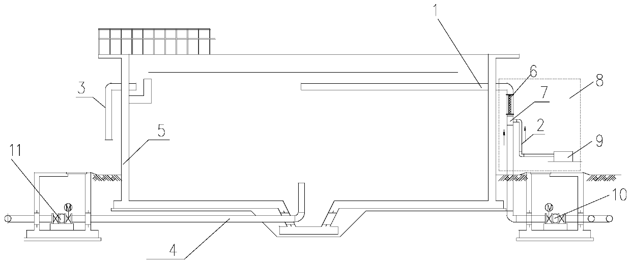
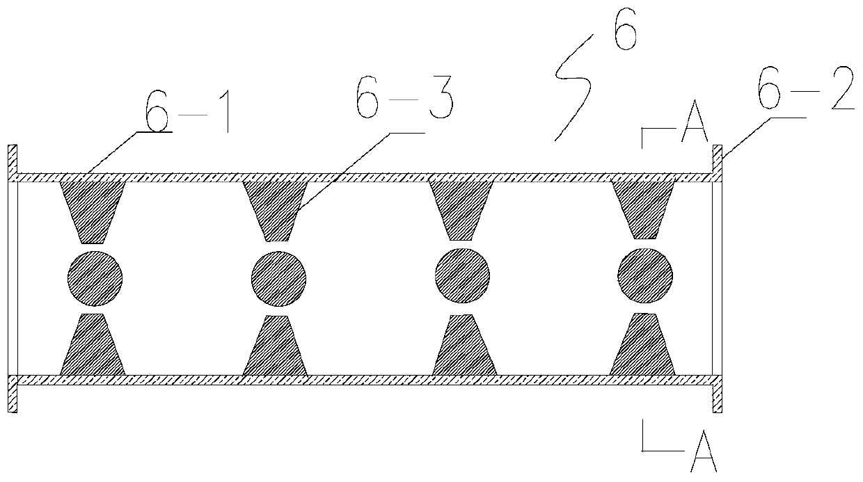
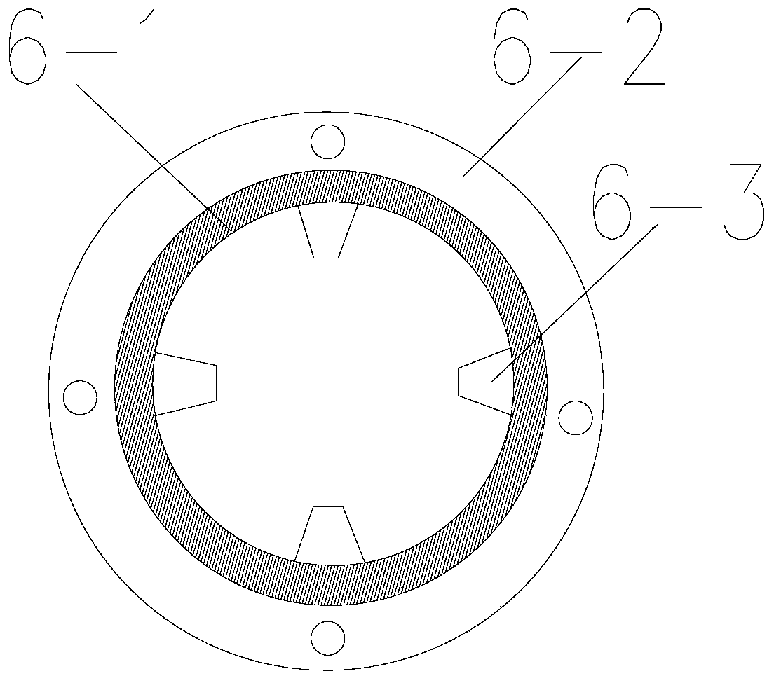
[0026] See the accompanying drawings for details. This embodiment provides a method to improve the separation efficiency of the sludge gravity concentration tank. Through the optimized coagulant dosing position and the method of setting the spoiler in the pipeline mixer, the coagulant in the tank can be increased. The contact time with sludge can improve the utilization rate of coagulant, enhance the effect of coagulation reaction and reduce the effect of coagulant dosage. The specific steps are as follows:

[0027] 1) In the body of the sludge thickening tank with a circular shape, the sludge inlet pipe is placed on the upper side wall of the sludge thickening tank body, the mud inlet pipe is connected with the coagulant dosing device, and the sludge lifting pump sends the sludge into the inlet mud pipe;

[0...


PUM

PropertyMeasurementUnit
lengthaaaaaaaaaa

Abstract

The invention relates to a method for improving the separation efficiency of a sludge gravity concentration tank. According to the method, spoilers are arranged through optimized coagulant adding positions and a pipeline mixer. According to the sludge gravity concentration tank, a sludge inlet pipe is connected with a coagulant dosing device; the coagulant dosing device comprises a coagulant dosing pump, a coagulant dosing pipe and the pipeline mixer; the pipeline mixer comprises a mixer barrel and the spoilers, the spoilers are evenly distributed on the inner wall of the cylindrical mixer barrel, the mixer barrel is fixedly connected with the sludge inlet pipe, an inlet of the mixer barrel is connected with the coagulant feeding pipe, and the coagulant feeding pipe is connected with the coagulant feeding pump. The beneficial effects are that the contact time of a coagulant and sludge is prolonged, the utilization rate of the coagulant is increased, and the coagulation reaction effectis enhanced through the optimized coagulant adding positions and the arranged spoilers.

Description

technical field [0001] The invention belongs to the field of sewage treatment, and in particular relates to a method for improving the separation efficiency of a sludge gravity concentration tank and the sludge gravity concentration tank. Background technique [0002] Gravity thickening is a widely used sludge thickening technology, which has the advantages of easy maintenance and management, and low operating costs. Gravity concentration is to use the relative density difference between the solid particles in the sludge and the water to realize the concentration of the sludge. Coagulants are widely used to achieve faster and more efficient separation of solid particles from water. Coagulation refers to the process of aggregating colloidal particles and suspended solids in water by adding chemicals (coagulants). The use of coagulant can greatly improve the efficiency of sludge thickening. [0003] Patent Document Publication No. 208562104U discloses a sludge thickening ta...

Claims


Application Information

Patent Timeline
Patent Type & Authority Applications(China)
IPC IPC(8): C02F1/52
CPCC02F1/5281C02F2001/007C02F2201/002C02F2201/007
Inventor 王宏田王庆刘翊王传山张惠源马丽媛王宏超李宝成王吉桐潘倩
Owner 天津泰达新水源科技开发有限公司
Why Eureka
Try Eureka