Radio positioning method and system based on departure angles

A technology for radio positioning and positioning signals, applied in radio wave measurement systems, services based on location information, positioning and other directions, can solve the problems of complex system implementation and high synchronization requirements, and achieve high system capacity, simple system structure and algorithm flow. Effect

Active Publication Date: 2020-08-11
SHANGHAI JIAO TONG UNIV
View PDF7 Cites 1 Cited by
  • Summary
  • Abstract
  • Description
  • Claims
  • Application Information

AI Technical Summary

Problems solved by technology

[0003] In summary, existing radio positioning methods, especially indoor radio positioning methods, have defects such as high synchronization requirements and complex system implementation.

Method used


Image

  • Radio positioning method and system based on departure angles
  • Radio positioning method and system based on departure angles
  • Radio positioning method and system based on departure angles

Examples


Embodiment 1

[0091] Embodiment 1: Radio positioning of two base stations based on departure angle;

[0092] Please also see Figure 2 to Figure 3 .

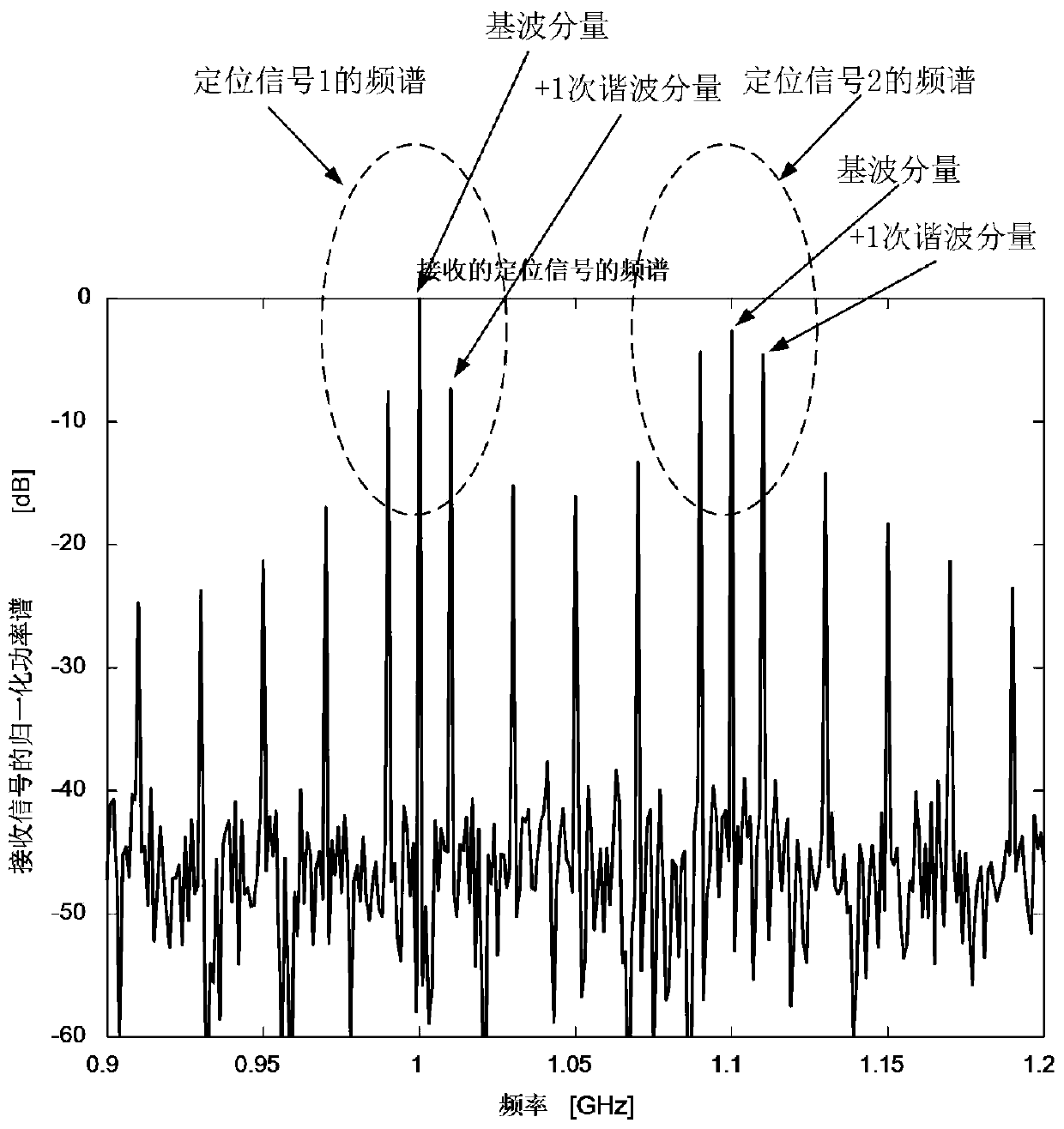
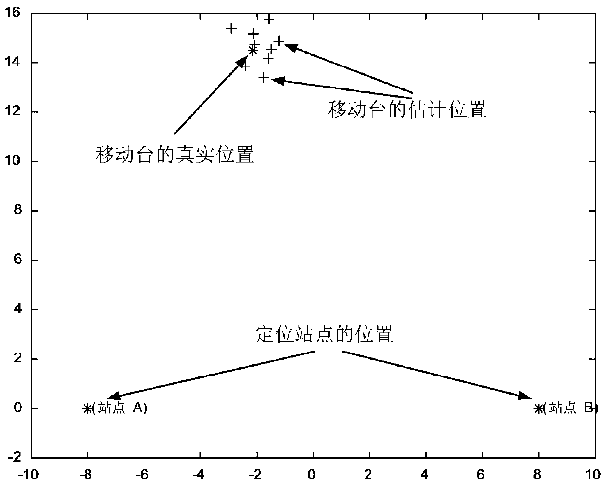
[0093] This embodiment provides two base station radio positioning based on departure angle. It is assumed that base station 1 transmits a single-frequency signal with a carrier frequency of 1 GHz, and base station 2 transmits a single-frequency signal with a carrier frequency of 1.1 GHz. The distance between the two antenna units on the two base stations is 15cm, and the normal directions of the antenna arrays of the base stations all point to the true north. The distance between the two base stations is 16 meters.

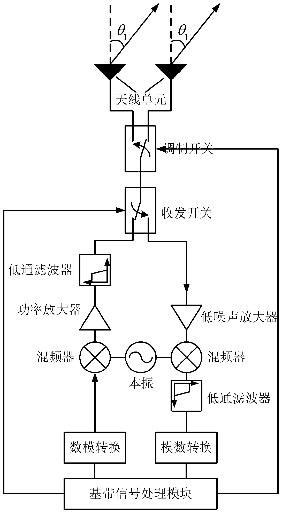
[0094] The positioning signals transmitted by the two positioning base stations are periodically modulated, the modulation period is 0.1us, and the corresponding frequency is 10MHz. That is, within one modulation cycle (100 ns), the positioning signal transmitted in the first half cycle is connected to the antenna unit 1, an...

Embodiment 2

[0097] Embodiment 2: root mean square of positioning errors under different signal-to-noise ratio conditions;

[0098] Please also see Figure 4 .

[0099] In order to verify the accuracy of the positioning method provided by the present invention under different signal-to-noise ratio conditions. Set the SNR from -10dB to +20dB with a step of 2dB. Under each signal-to-noise ratio condition, 1000 Monte Carlo simulations are performed, and the root mean square of the positioning error under the condition of the signal-to-noise ratio is calculated. Set the orientation of the mobile terminal relative to the positioning base station 1 as +25°, and the orientation relative to the positioning base station 2 as -45°. Conditions such as the carrier frequency, modulation frequency, and cycle number of the transmitted positioning signal are the same as those in the first embodiment. After Monte Carlo simulation, the root mean square value of the positioning error obtained under diffe...


PUM


Abstract

The invention provides a radio positioning method and system based on a departure angle. The method comprises the following steps: a base station positioning step: a base station end transmits a positioning signal, wherein the positioning signal comprises the true north position of the base station and base station identification code information, and a mobile end estimates the orientation of themobile end relative to the base station end by receiving the positioning signal transmitted by the base station end and then realizes self-positioning through triangulation; a modulation step: periodically modulating the signal transmitted by the base station end according to the single-pole double-throw radio frequency switch, and in one modulation period, respectively connecting the positioningsignal to the two antenna units and radiating the positioning signal to the space; and a calculation step: the mobile terminal calculates a fundamental component and a first harmonic component in thereceived positioning signal, and estimates the orientation of the mobile terminal relative to the base station terminal by using the mathematical relationship between the fundamental component and thefirst harmonic component. Multiple times of data interaction between the positioning base stations and between the positioning base stations and the mobile terminal are not needed, the system capacity is higher, and the system structure and the algorithm flow are simple.

Description

technical field [0001] The present invention relates to the technical field of radio positioning, in particular to a radio positioning method and system based on departure angle. In particular, it relates to a radio positioning system in which a mobile terminal realizes triangulation positioning by estimating the departure angle of a signal transmitted by a positioning base station. Background technique [0002] The existing radio positioning methods mainly include global positioning system, time of arrival (ToA), time difference of arrival (TDOA), angle of arrival (AoA) and so on. Among them, the global positioning system mainly includes the GPS system of the United States, the Galileo system of Europe, the GLONASS system of Russia, and the Beidou system of China, etc., which are mainly used in wide-area outdoor positioning. Attenuation, less effective or unusable. Time-of-arrival positioning and time-difference-of-arrival positioning use the arrival time or time differen...

Claims


Application Information

Patent Timeline
Patent Type & Authority Applications(China)
IPC IPC(8): H04W4/02H04W64/00G01S5/26
CPCG01S5/26H04W4/023H04W4/025H04W4/026H04W64/00
Inventor 贺冲曹岸杰李海亭易观理
Owner SHANGHAI JIAO TONG UNIV
Why Eureka
Try Eureka