Sheet metal part blanking die

A technology for sheet metal parts and molds, applied in the direction of manufacturing tools, metal processing equipment, feeding devices, etc., can solve problems such as reducing work efficiency, improving labor intensity of staff, and not mentioning it, reducing the probability of elastic deformation, improving Labor intensity, the effect of ensuring stability

Active Publication Date: 2020-08-14
青岛和成源金属制品有限公司
View PDF7 Cites 1 Cited by
  • Summary
  • Abstract
  • Description
  • Claims
  • Application Information

AI Technical Summary

Problems solved by technology

[0003] However, there are the following problems in the process of manufacturing and processing the existing metal sheets into frame structures: a. It is necessary to manually cut the corresponding sheets of the sheet metal. Multiple corners of the plate are cut, which cannot guarantee the cutting angle of the plate, which affects the quality of the frame made of the metal plate. b. It is necessary to manually shape the cut plate, and it is impossible to realize the integrated operation of metal plate cutting and stamping forming. Reduce the work efficiency, increase the labor intensity of the staff, and increase the cost of processing the metal sheet into a frame structure
[0004] For the technical problems existing in the current sheet metal processing process, personnel in related technical fields have made appropriate improvements after research, such as the Chinese utility model patent cutting and bending machine with the patent number 2017215608574, which can carry out multiple processes at the same time. The bending and cutting operation of the root welding strip, however, does not mention the above-mentioned problems

Method used


Image

  • Sheet metal part blanking die
  • Sheet metal part blanking die
  • Sheet metal part blanking die

Examples


Embodiment Construction

[0026] The embodiments of the present invention will be described in detail below with reference to the accompanying drawings, but the present invention can be implemented in many different ways defined and covered by the claims.

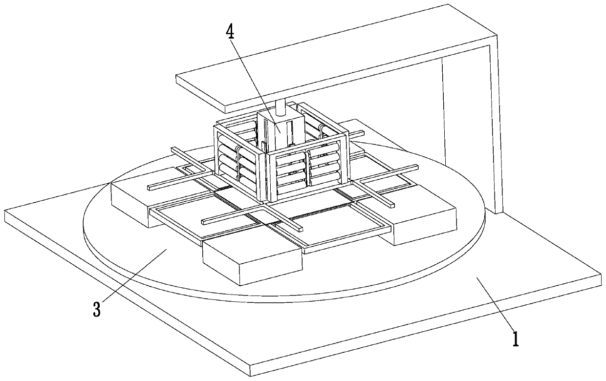
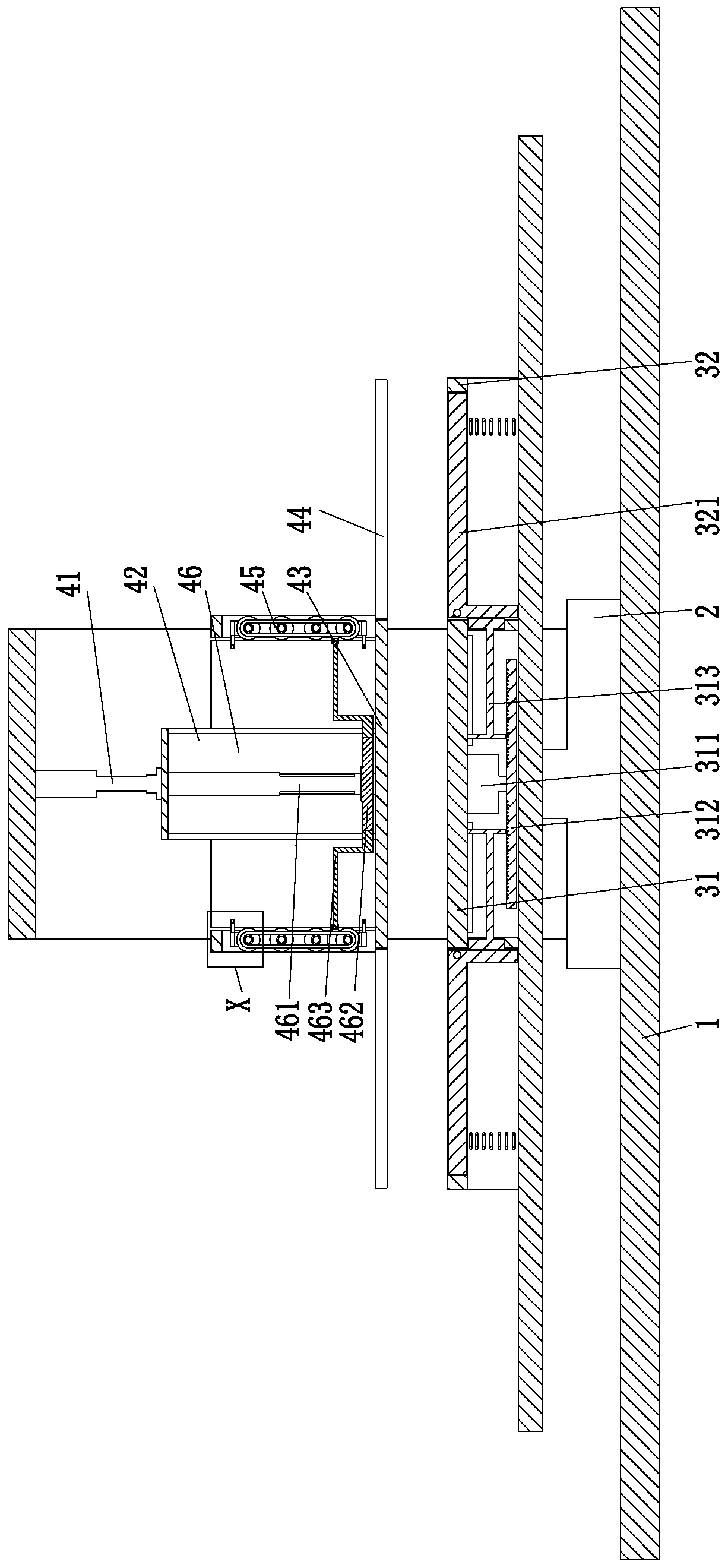
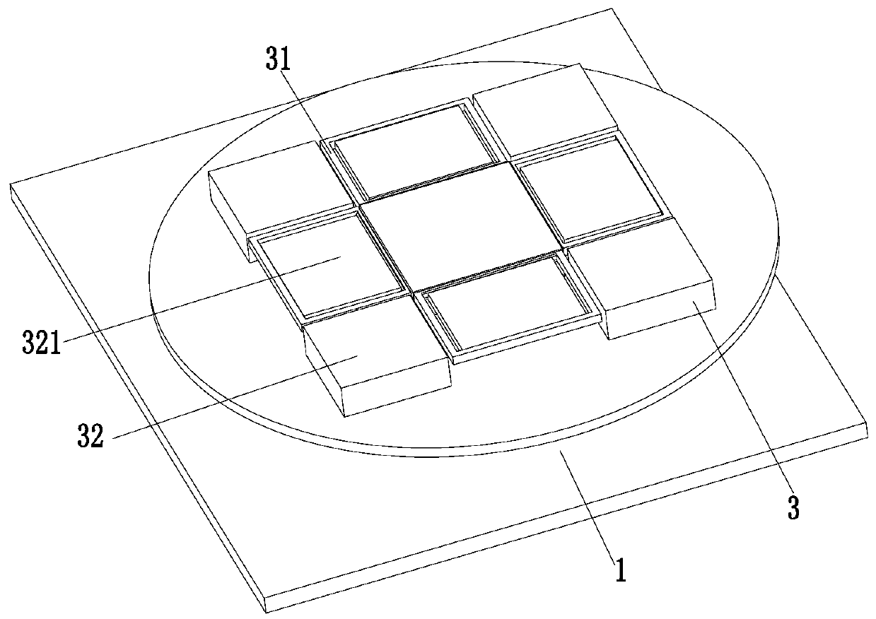
[0027] Such as Figure 1 to Figure 7 As shown, a blanking die for sheet metal parts includes a frame 1, a rotating motor 2 is installed in the middle of the frame 1, a bottom auxiliary device 3 is installed on the upper end of the rotating motor 2, and a top is installed on the inner wall of the upper end of the frame 1. punching device 4;

[0028] The bottom auxiliary device 3 includes a rotating plate installed on the rotating motor 2, a placement frame 31 is installed on the rotating plate, U-shaped auxiliary frames 32 are installed on the sides of the placing frame 31, and auxiliary frames 32 are evenly arranged on the rotating plate. Block 33, the auxiliary block 33 is located between two adjacent U-shaped auxiliary frames 32, and a right-angl...


PUM


Abstract

The invention relates to a sheet metal part blanking die. The sheet metal part blanking die comprises a rack, a rotating motor is arranged in the middle of the rack, a bottom auxiliary device is arranged at the upper end of the rotating motor, and a top blanking device is arranged on the inner wall of the upper end of the rack. The sheet metal part blanking die can solve the following problems ina process of manufacturing and machining an existing metal plate into a frame structure: a, a plate needs to be manually cut, but the manual cutting efficiency is low, the metal plate cannot be integrally cut at the same time, a plurality of corners of the metal plate need to be cut step by step, the cutting angle of the plate cannot be guaranteed, and the quality of a frame manufactured by the metal plate is affected can be solved; and b, the cut plate needs to be manually formed and machined, integrated operation of cutting and punch forming of the metal plate cannot be achieved, the workingefficiency is reduced, the labor intensity of workers is improved, and the cost of machining the metal plate into the frame structure is increased.

Description

technical field [0001] The invention relates to the technical field of sheet metal processing, in particular to a blanking die for sheet metal parts. Background technique [0002] Sheet metal processing is called sheet metal processing. Specifically, for example, using plates to make chimneys, iron barrels, fuel tanks, ventilation pipes, elbows, round places, funnel shapes, etc. The main processes are cutting, bending buckle, bending forming, welding, riveting, etc. It is common in daily life to process the metal sheet into a frame for storage. In the process of processing the metal sheet into a frame structure, the entire sheet is cut, and the excess waste is cut and then bent and welded into a frame. is the common way. [0003] However, there are the following problems in the process of manufacturing and processing the existing metal sheets into frame structures: a. It is necessary to manually cut the corresponding sheets of the sheet metal. Multiple corners of the plat...

Claims


Application Information

Patent Timeline
IPC IPC(8): B21D35/00B21D43/28
CPCB21D35/002B21D43/282
Inventor 汪煜胡峰
Owner 青岛和成源金属制品有限公司
Why Eureka
Try Eureka