Eureka AIR delivers breakthrough ideas for toughest innovation challenges, trusted by R&D personnel around the world.

Drilling fluid circulating system

A technology of circulation system and drilling fluid, which is used in earth-moving drilling, flushing wellbore, wellbore/well components, etc., and can solve the problems of assistant driller's personal safety threat, slow opening speed, influence of mud flow, etc.

Active Publication Date: 2020-08-14
SINOPEC SSC +1
View PDF16 Cites 0 Cited by
  • Summary
  • Abstract
  • Description
  • Claims
  • Application Information

AI Technical Summary

Problems solved by technology

If the sub-driller enters the high-pressure area to switch the valve under the pressure-suppressed state, the leakage of the valve will pose a threat to the personal safety of the sub-driller, posing a safety hazard
Moreover, it is difficult to open the valve and the opening speed is slow when it is under pressure, which may easily lead to gate erosion
[0007] In order to prevent heavy objects from smashing the screw rod of the valve, there is a valve stem guard outside the screw rod. The valve stem guard protects the screw rod, and at the same time, it also makes it difficult to distinguish the open and closed states of the valve.
If the valve is in a half-open state, it is easy to affect the mud flow, and even cause erosion to the gate

Method used


Image

  • Drilling fluid circulating system
  • Drilling fluid circulating system
  • Drilling fluid circulating system

Examples


Embodiment Construction

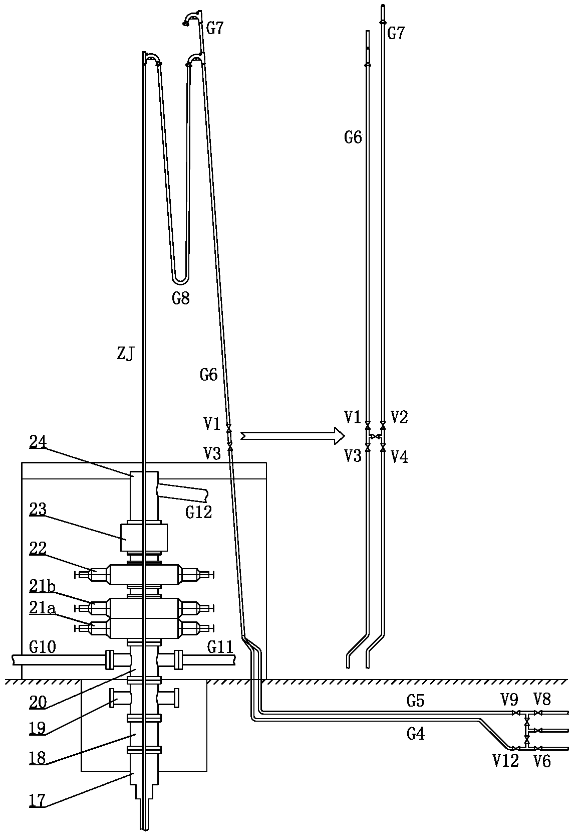
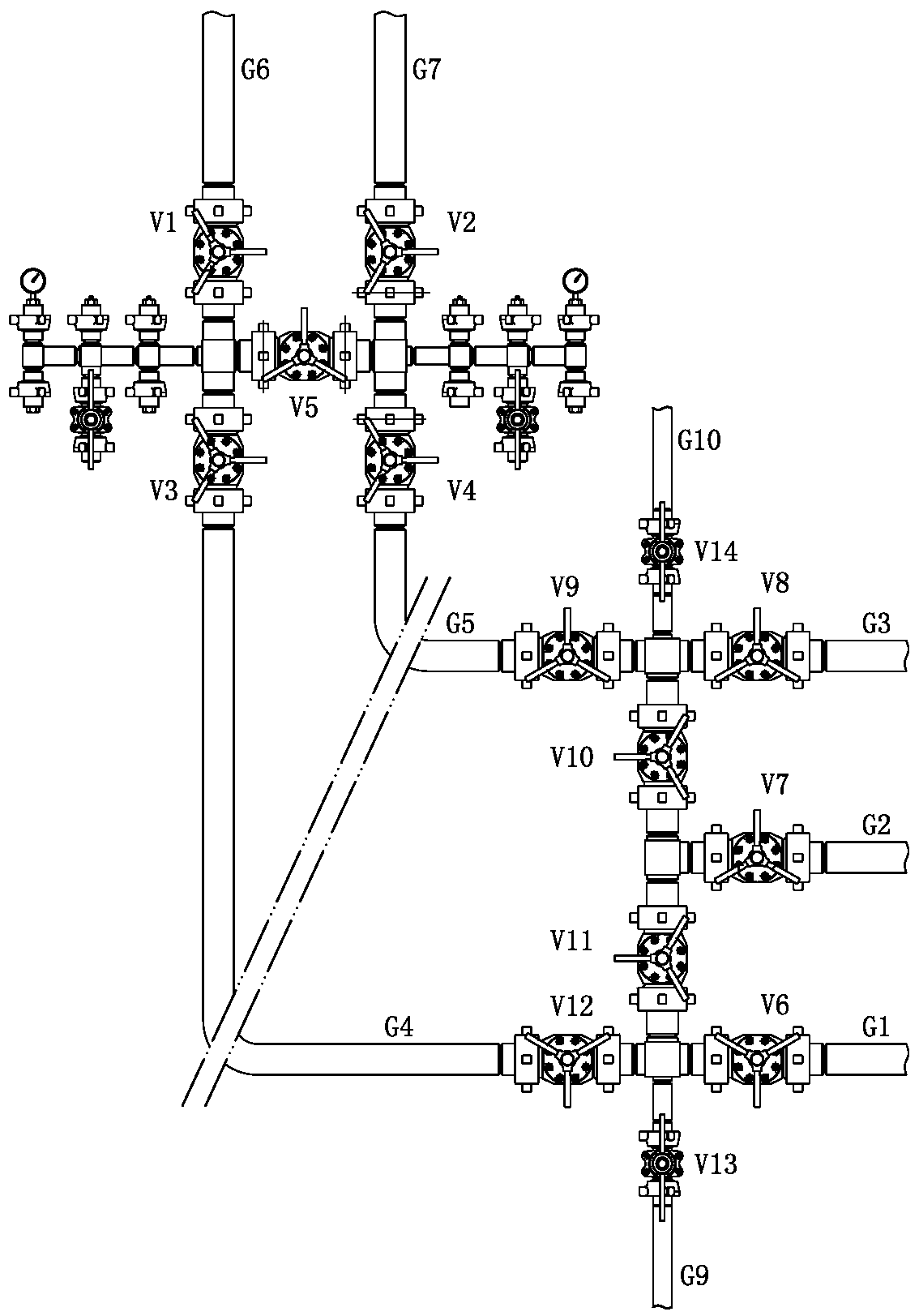
[0037] like figure 1 and figure 2As shown, the drilling fluid circulation system of the present invention includes a drill floor valve group and a surface valve group, the drill floor valve group includes valve one V1 to valve five V5, valve one V1 and valve three V3 are connected in series in the low riser G6 and valve one V1 is on the top, valve two V2 and valve four V4 are connected in series in the high riser G7 and valve two V2 is on the top, there is a low riser bypass port between valve one V1 and valve three V3, valve two V2 and valve four V4 There is a high riser bypass port between them, and the low riser bypass port is connected to the high riser bypass port through valve five V5; the ground valve group includes valve six V6 to valve twelve V12, and the No. 1 pump outlet pipe G1 is in turn Through valve six V6 and valve twelve V12, it is connected with the right ground pipe G4, and the outlet of the right ground pipe G4 is connected with the lower end of the low r...


PUM


Abstract

The invention relates to a drilling fluid circulating system. A valve I and a valve III of a drill floor valve group are connected to a low vertical pipe in series, the valve I is located at the upperpart, a valve II and a valve IV are connected to a high vertical pipe in series, the valve II is located at the upper part, and the valve I and the valve III are connected with the valve II and the valve IV through a valve V; a ground valve group comprises a valve VI and the valve XII, an outlet pipe of a No.1 pump sequentially passes through the valves VI-XII to be connected with a right groundpipe, and an outlet of the right ground pipe is connected with the lower end of the lower vertical pipe; an outlet pipe of a No.3 pump sequentially passes through the valve VIII and the valve IX to beconnected with a left ground pipe, and an outlet of the left ground pipe is connected with the lower end of the high vertical pipe; an outlet pipe of a No.2 pump is connected with the valve VII, an outlet of the valve VII is connected with the valve X and the valve XI through a tee joint respectively, the other end of the valve X is connected with a bypass port of a four-way joint of an inlet ofthe valve IX, and the other end of the valve XI is connected with a bypass port of a four-way joint of an inlet of the valve XII. According to the system, slurry can be conveyed through the vertical pipes with different heights, slurry pumps can be reasonably switched, and normal displacement and pumping pressure are guaranteed.

Description

technical field [0001] The invention relates to a valve for an oil drilling rig, in particular to a drilling fluid circulation system, and belongs to the technical field of valves for an oil drilling rig. Background technique [0002] During the drilling process, one or more mud pumps spray high-pressure fluid to the bottom of the well through manifolds, gate groups, hoses, drilling tools and drill bit water holes, forming high-pressure fluid to wash the bottom of the well and dislodging the solids in the wellbore. Phase particles are carried out. The fluid drilling fluid participating in the circulation has the following functions: one is to clean the bottom of the well, suspend and carry cuttings, and keep the borehole clean; the other is to balance the formation pressure, stabilize the well wall, and prevent well collapse, blowout, and lost circulation; 1. To help the drill bit break rocks; 4. To transmit power for downhole dynamic drilling tools; 5. To cool the drill bi...

Claims


Application Information

Patent Timeline
IPC IPC(8): E21B21/10
CPCE21B21/106E21B21/103
Inventor 樊继强郑雪坤吴枝国董云飞王磊杨守生刘鑫丁科艳
Owner SINOPEC SSC
Why Eureka
Eureka Blog
Learn More