Multifunctional mobile test device

A test device and multi-functional technology, applied in the mechanical field, can solve the problems of test personnel and laboratory equipment danger, difficulty in placement process, and influence on test results, so as to improve test efficiency and accuracy, shorten test time, and reduce manpower resource effect

Active Publication Date: 2020-08-14
HARBIN INST OF TECH
View PDF6 Cites 0 Cited by
  • Summary
  • Abstract
  • Description
  • Claims
  • Application Information

AI Technical Summary

Problems solved by technology

[0004] In the prior art, for the low-cycle repeated loading test, there are the following disadvantages: (1) How to accurately place the specimen such as the column or the shear wall in the designated position is a very difficult thing
(2) Most of them use the bridge crane in the laboratory to put it into the designated position step by step. The placement process is difficult, and it needs to be placed multiple times due to the influence of the upper beam. This will consume a lot of time and manpower, and in the hoisting process Potential hazard to test personnel and laboratory equipment
(3) During the placement of the specimen, if the center of the specimen and the center of the actuator on the reaction wall are not on the same line, the test results will be affected
(4) If specimens with different heights are loaded, it is necessary to hire professionals to move the height of the beam, which not only takes time, but also costs a certain amount of money
For the bending test of the beam, most of the supports are patchwork or temporary welding, which will waste a lot of time

Method used


Image

  • Multifunctional mobile test device
  • Multifunctional mobile test device
  • Multifunctional mobile test device

Examples


Embodiment Construction

[0029] The technical solutions in the embodiments of the present invention will be clearly and completely described below in conjunction with the drawings in the embodiments of the present invention.

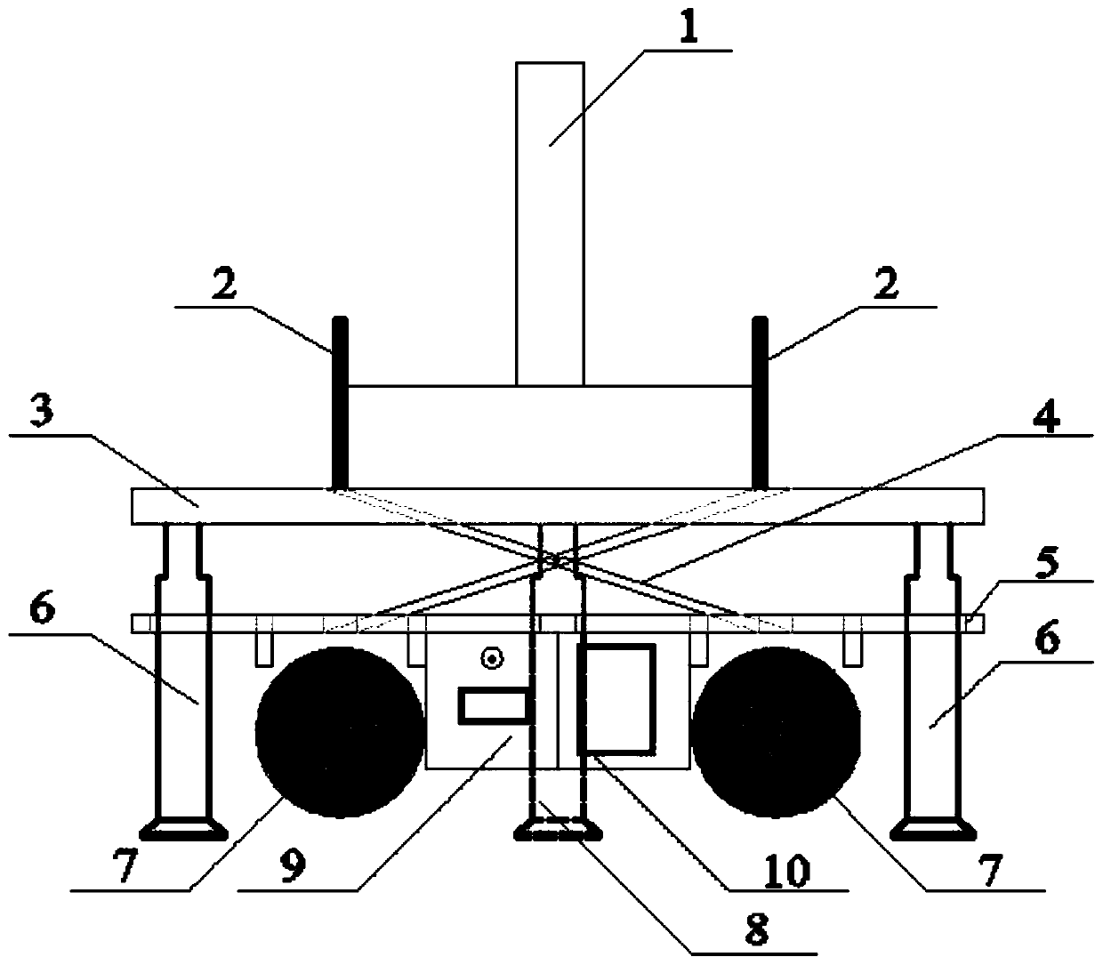
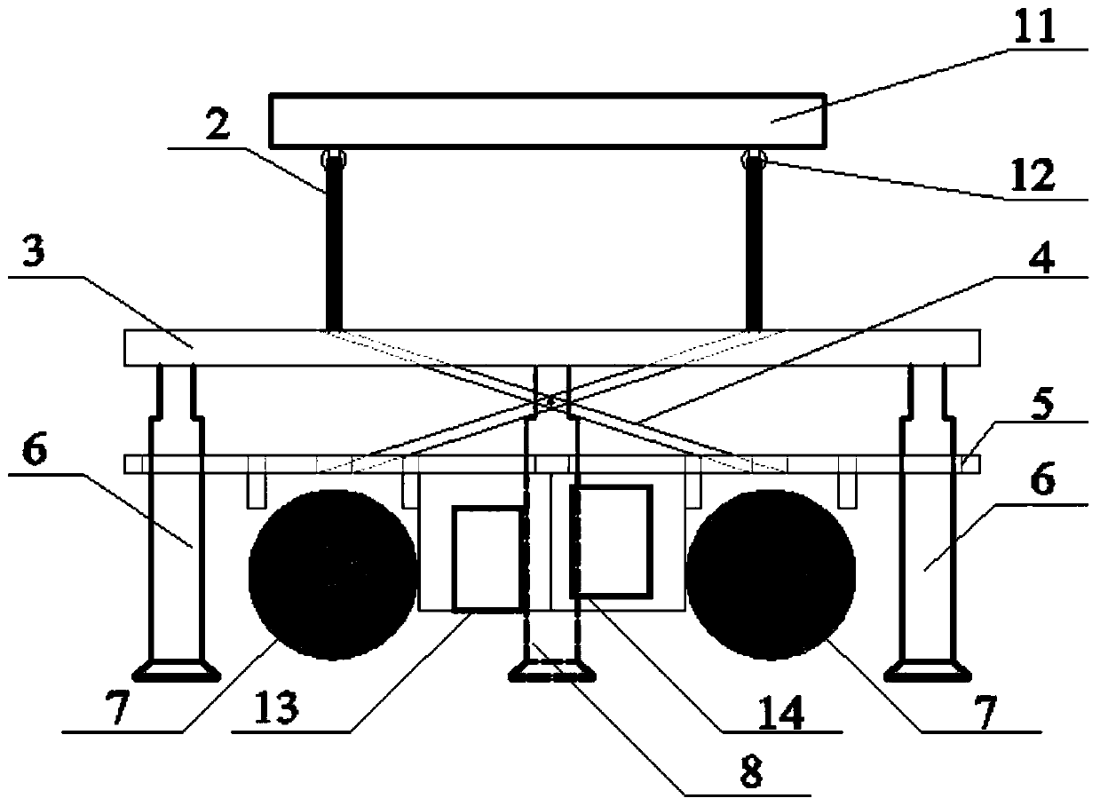
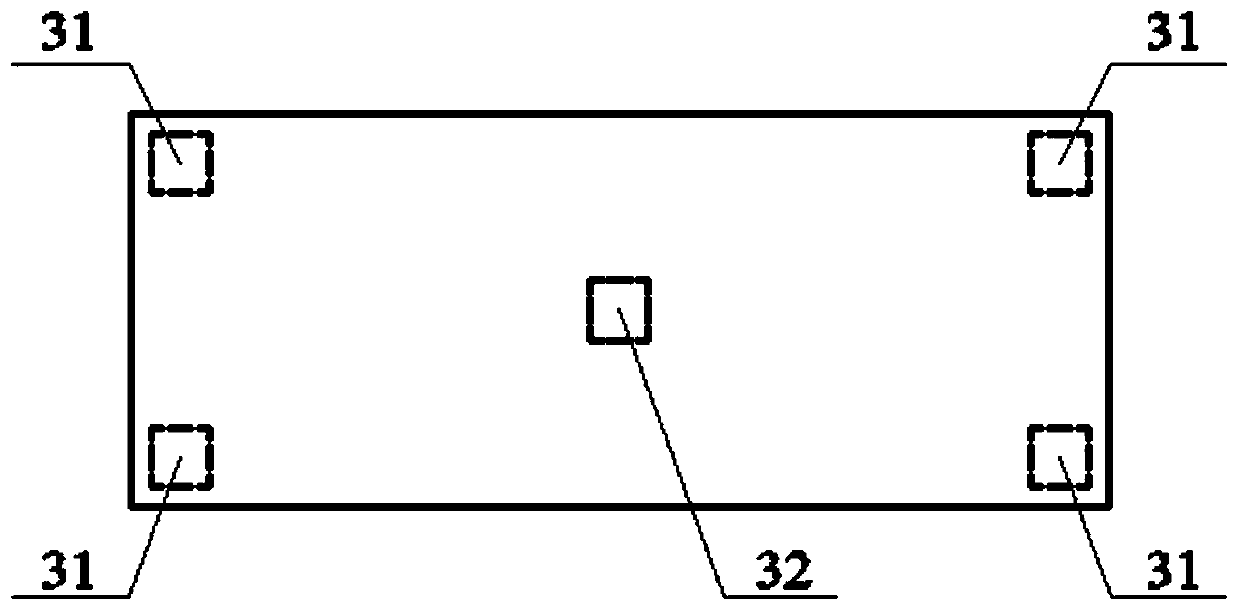
[0030] see Figure 1-10 Describe this embodiment, a multifunctional mobile test device, which includes a mobile splint 2, a lifting plate 3, a scissor support hydraulic mechanism 4, a chassis 5, a corner jack 6, a moving mechanism, a middle jack 8, a fuel tank 9, and a hydraulic control device 10. Battery 13 and signal control device 14, the lower part of the chassis 5 is provided with a moving mechanism, the upper part of the chassis 5 is connected to the lifting plate 3 through the scissors support hydraulic mechanism 4, and the four corners of the lifting plate 3 are respectively provided with corner jacks 6 , the center of the lifting plate 3 is connected to the middle jack 8, the upper part of the lifting plate 3 is provided with a track 42, the number of the moving splint ...


PUM


Abstract

The invention provides a multifunctional mobile test device, and belongs to the technical field of machinery, thereby solving a problem that test pieces are difficult to transport and load in existinganti-seismic tests of columns, shear walls and other components and bending tests of beams. The device comprises movable clamping plates, a lifting plate, a diagonal bracing hydraulic mechanism, a chassis, corner jacks, a moving mechanism, a middle jack, an oil tank, a hydraulic control device, a storage battery and a signal control device; the moving mechanism is arranged at the lower part of the chassis; the upper part of the chassis is connected with the lifting plate through the diagonal bracing hydraulic mechanism; the four corners of the lifting plate are respectively provided with thecorner jacks, the center of the lifting plate is connected with the middle jack, the upper part of the lifting plate is provided with a track, the number of the movable clamping plates is two, the twomovable clamping plates are both arranged in the track, and the movable clamping plates are used for fixing a test piece. The device is mainly used for anti-seismic tests of columns, shear walls andother components and bending tests of beams.

Description

technical field [0001] The invention belongs to the mechanical technical field for component loading in construction engineering or bridge engineering, and in particular relates to a multifunctional mobile test device. Background technique [0002] Seismic tests of building structures can be divided into pseudo-static load (low cycle repeated loading test) test, pseudo-dynamic load test, and dynamic loading test according to different test methods and test methods. Due to the advantages of relatively simple quasi-static load test equipment and the fact that the loading process can be controlled manually, quasi-static load tests are mostly used in the simulated seismic action tests of columns or shear walls and other components. Therefore, how to make the test process simple, fast and accurate has high requirements for the preparation work before the test. [0003] As one of the main components of bridges and building structures, beams are typical flexural components. Theref...

Claims


Application Information

Patent Timeline
IPC IPC(8): G01M7/02G01N3/36G01N3/20G01N3/02
CPCG01M7/02G01N3/36G01N3/20G01N3/02G01N2203/0005G01N2203/0023G01N2203/0048G01N2203/0264
Inventor 李爽赵建军翟长海
Owner HARBIN INST OF TECH
Why Eureka
Try Eureka