
Array antenna error correction method suitable for field of millimeter wave vehicle-mounted radar

An array antenna and vehicle radar technology, applied in radio wave measurement systems, measurement devices, instruments, etc., can solve the problems of array element amplitude and phase error, DOA estimation algorithm performance degradation, failure and other problems, and achieve the effect of reducing the impact

Active Publication Date: 2020-08-14
SOUTHEAST UNIV
View PDF10 Cites 12 Cited by
  • Summary
  • Abstract
  • Description
  • Claims
  • Application Information

AI Technical Summary

Problems solved by technology

In practical engineering applications, due to the existence of various errors (array element amplitude and phase error, array element mutual coupling error, array element position error, etc.), the actual array flow pattern does not match the theoretical value, making the existing DOA estimation algorithm Performance drops significantly, or even fails
Therefore, the ubiquity of array errors has always been a bottleneck that hinders the high-resolution spatial spectrum estimation technology from theory to engineering application.

Method used


Image

  • Array antenna error correction method suitable for field of millimeter wave vehicle-mounted radar
  • Array antenna error correction method suitable for field of millimeter wave vehicle-mounted radar
  • Array antenna error correction method suitable for field of millimeter wave vehicle-mounted radar

Examples

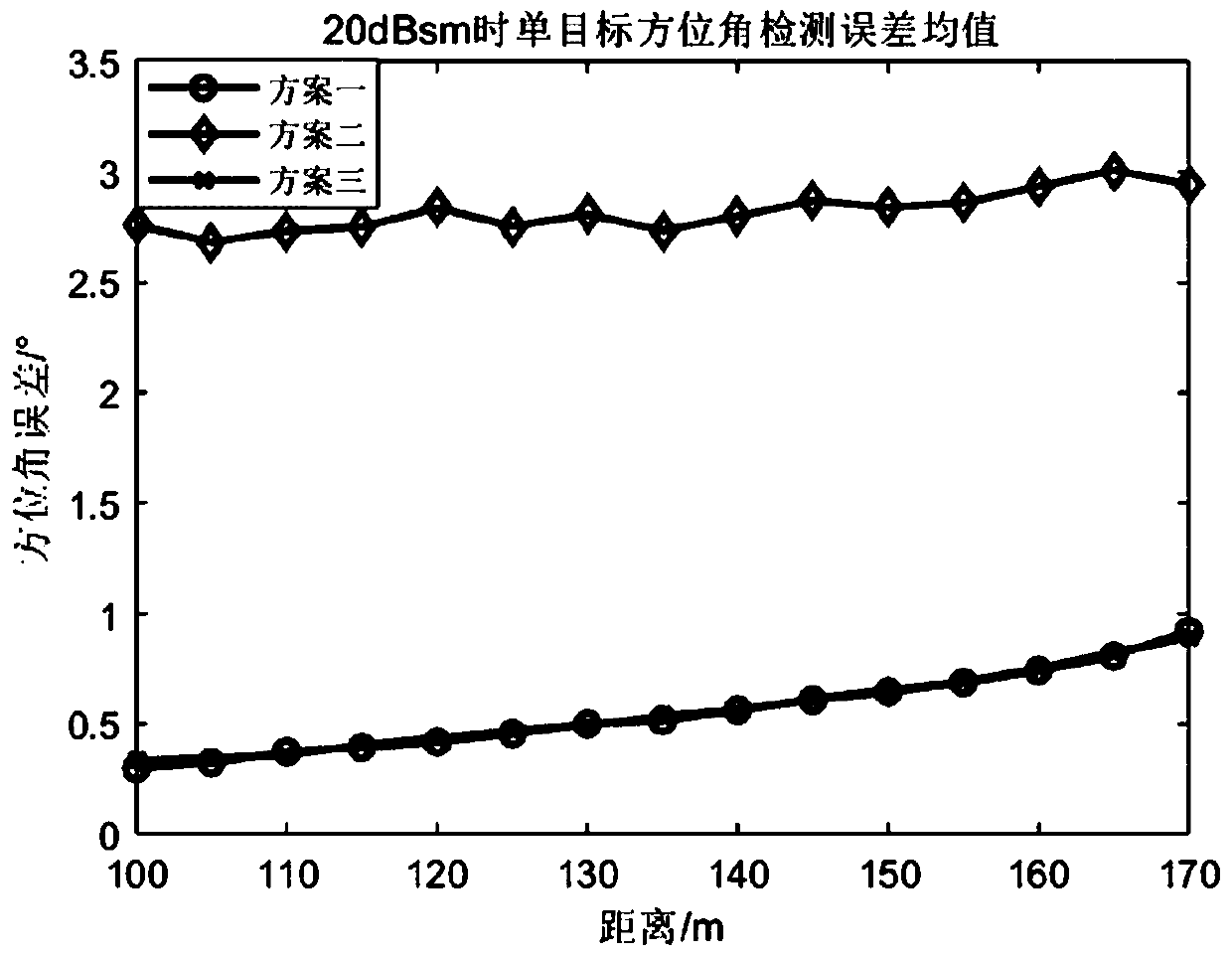
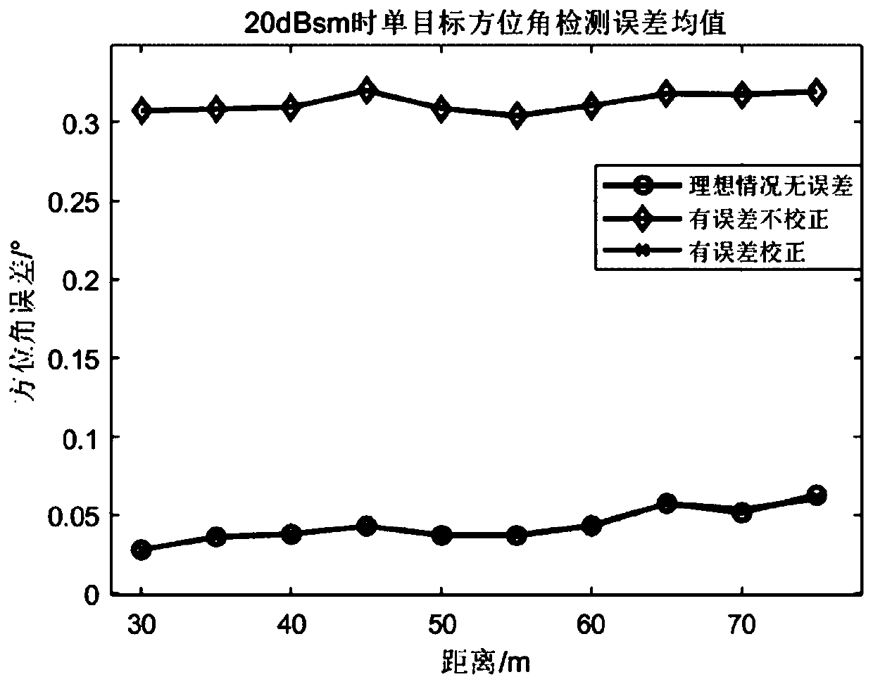
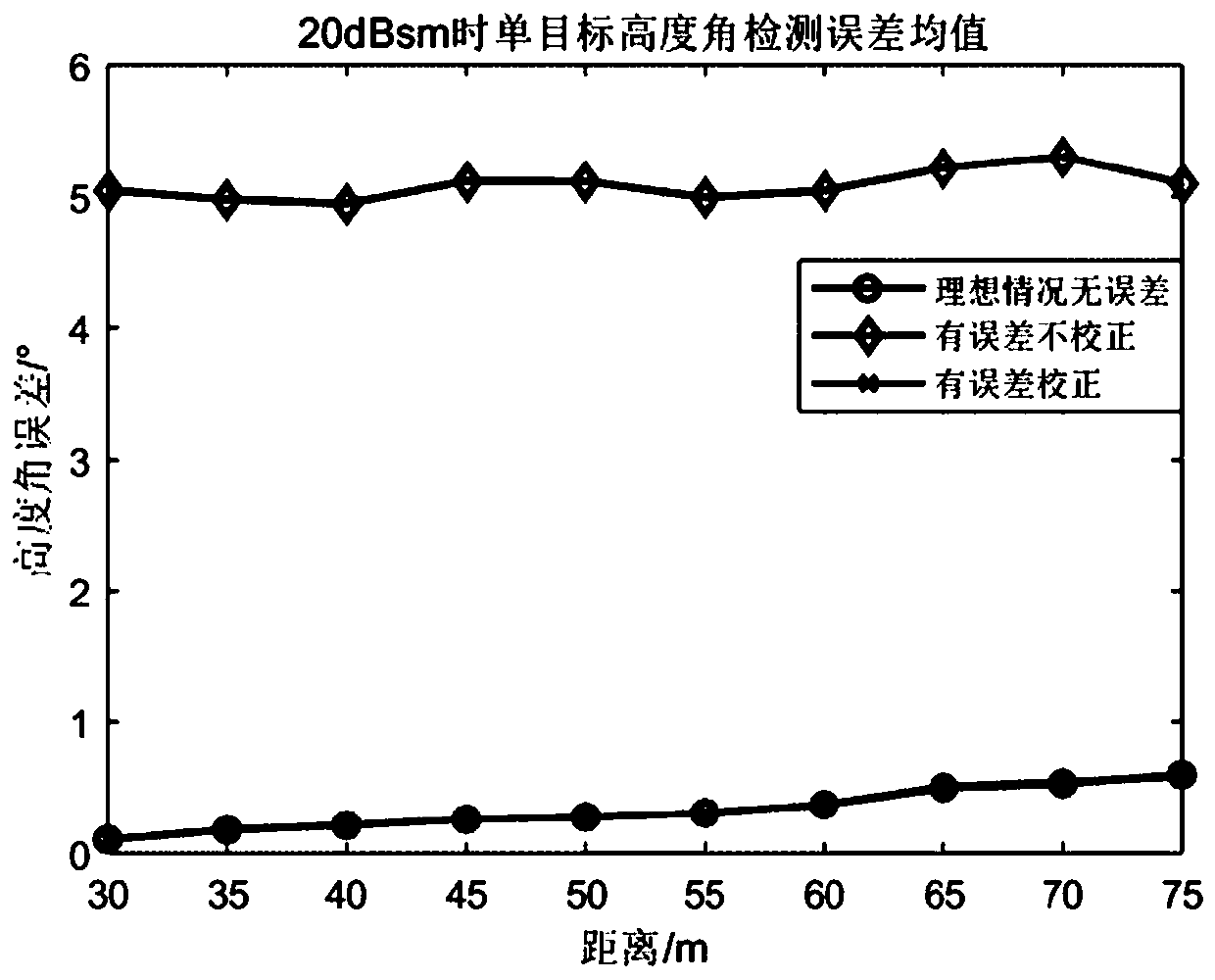

Embodiment Construction

[0084] Below in conjunction with specific implementation case, further illustrate the present invention, it should be understood that these embodiments are only used to illustrate the present invention and are not intended to limit the scope of the present invention, after reading the present invention, those skilled in the art will understand various equivalent forms of the present invention All modifications fall within the scope defined by the appended claims of the present application.

[0085] The present invention proposes an array antenna error self-correction method applicable to the field of millimeter-wave vehicle radar, the method comprising the following steps:

[0086] Step 1: Pre-set two targets with known radial distance, velocity, and azimuth angle information from the radar, as an auxiliary signal source for array antenna phase correction. In the microwave anechoic chamber, the radar sends electromagnetic waves to the two determined targets , and receive its e...


PUM


Abstract

The invention discloses an array antenna error self-correction method suitable for the field of millimeter wave vehicle-mounted radar. The method comprises the following steps: firstly, an array antenna error model is established; the model is divided into a feeder length error class and an antenna spacing error class; secondly, two targets with known position information are set; phase information on a corresponding specific distance-Doppler unit is used; a relative ideal position deviation estimation distance of the array antenna and a fixed phase error estimation angle of the array antennaare calculated to complete self-correction of the antenna array; and finally, a phase compensation scheme and an airspace steering vector are corrected through the relative ideal position deviation ofthe antenna and the fixed phase error estimation of the array antenna to complete error correction of the array antenna. The accuracy of subsequent parameter estimation is greatly improved.

Description

technical field [0001] The invention belongs to the field of radar signal processing, in particular to an array antenna error correction method suitable for the field of millimeter wave vehicle radar. Background technique [0002] Typical ADAS applications such as Adaptive Cruise Control (ACC), Blind Spot Detection (BSD) and Forward Collision Warning (FCW) require high performance sensors. Compared with other sensors such as cameras, ultrasonic radars, and lidars, vehicle-mounted millimeter-wave radars have an irreplaceable role and status in the field of unmanned driving due to their small size, low cost, and all-weather adaptability. A hotspot of research in both academia and industry. Different transmission waveforms have different characteristics and applicable scenarios, which are the main factors that determine the performance of the vehicle-mounted millimeter-wave radar system. Among them, chirp continuous wave is widely used in automotive millimeter-wave radar prod...

Claims


Application Information

Patent Timeline
IPC IPC(8): G01S7/40
CPCG01S7/4052G01S7/4026G01S7/4086
Inventor 黄永明李杨宋依欣毛子焕刘晨文邵文韬
Owner SOUTHEAST UNIV
Learn More