S-band and C-band double-frequency controllable high-power microwave device

A high-power microwave and microwave device technology, applied in the field of S, can solve the problems of strong guiding magnetic field, large volume, high energy consumption, etc., and achieve the effect of reducing energy demand, reducing system volume, and simple structure size

Active Publication Date: 2020-08-14
INST OF APPLIED ELECTRONICS CHINA ACAD OF ENG PHYSICS
View PDF14 Cites 0 Cited by
  • Summary
  • Abstract
  • Description
  • Claims
  • Application Information

AI Technical Summary

Problems solved by technology

In the existing high-power microwave sources, high-impedance devices have high beam conversion efficiency, but generally require a strong guiding magnetic field, especially when the microwave source operates at a repetition rate, a bulky, high-energy-consuming The solenoid magnet system

Method used


Image

  • S-band and C-band double-frequency controllable high-power microwave device
  • S-band and C-band double-frequency controllable high-power microwave device

Examples


Embodiment 1

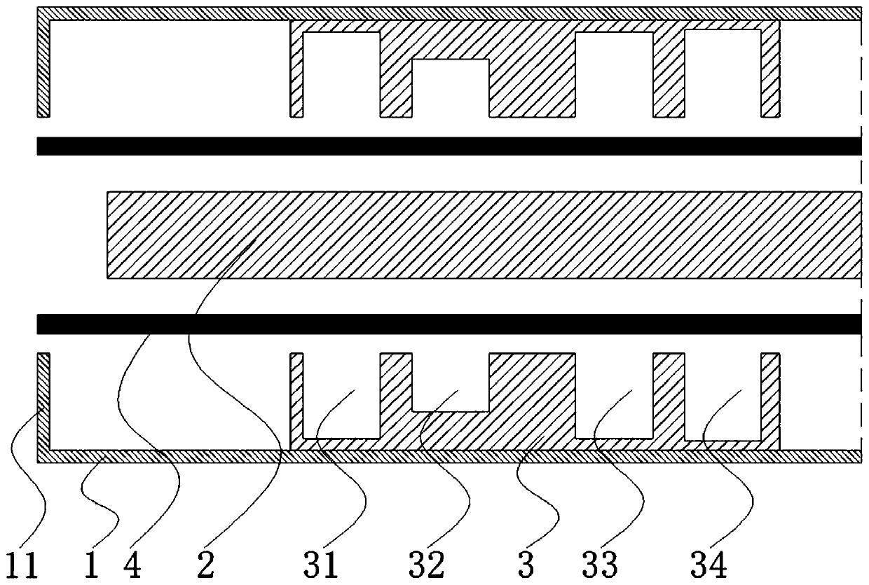
[0033] like figure 1 As shown, a kind of S, C-band dual-frequency controllable high-power microwave device of the present embodiment comprises a circular waveguide outer cylinder, an inner conductor coaxially arranged in the circular waveguide outer cylinder, arranged in the circular waveguide outer cylinder and coaxial with the circular waveguide outer cylinder. Coaxial hollow four-cavity slow-wave structure, the left end of the microwave device is provided with a circular closed structure with the same inner diameter as the four-cavity slow-wave structure, and a vacuum electron beam transmission channel is formed between the inner conductor and the four-cavity slow-wave structure. A ring-shaped electron beam transmitted in the transmission channel;

[0034] The four-cavity slow-wave structure can adjust its relative position in the microwave device, its total axial length is 170 mm, and its inner diameter is 76 mm;

[0035] The four-cavity slow-wave structure can axially ad...

Embodiment 2

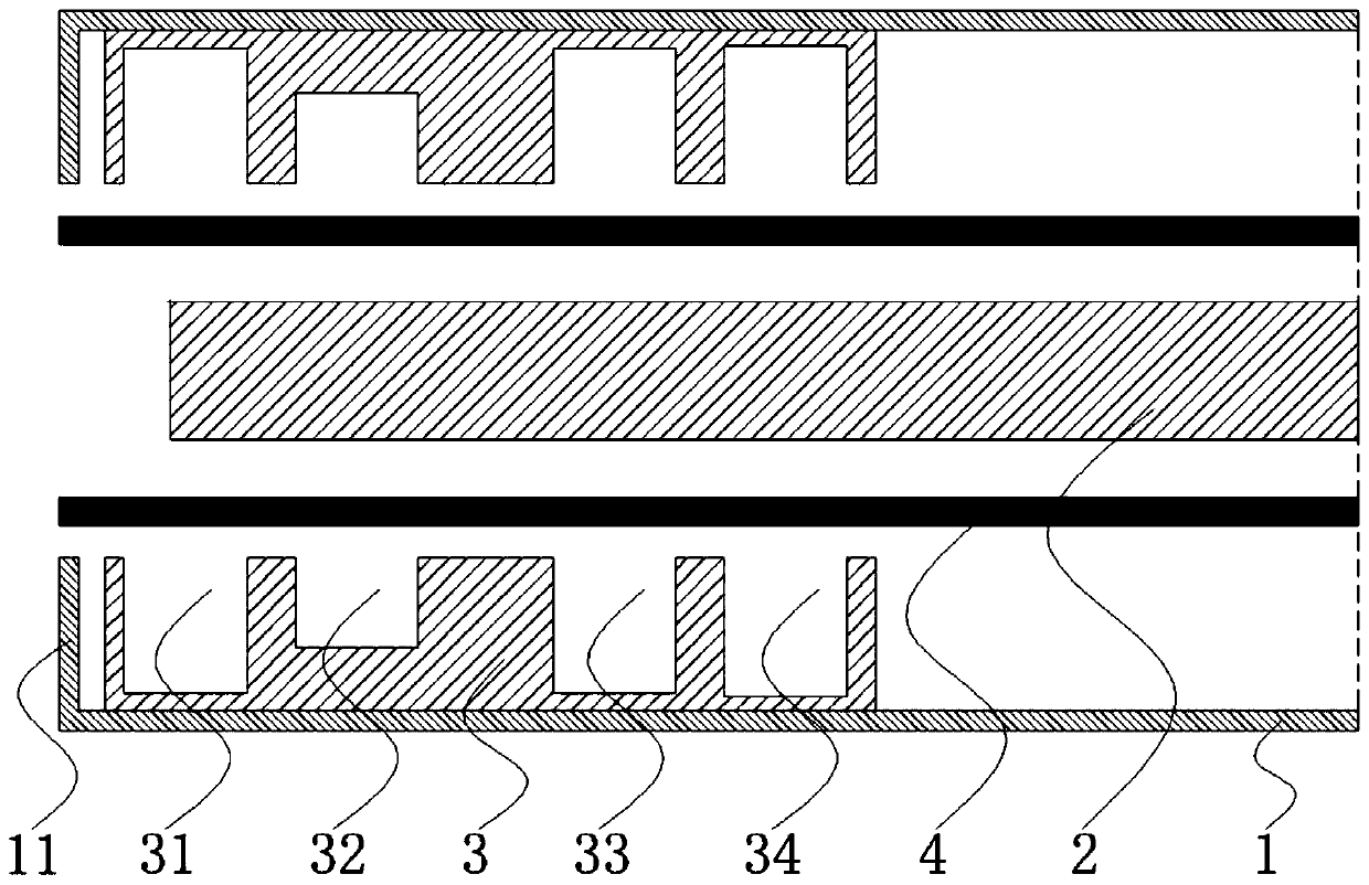
[0044] like figure 2 As mentioned above, the difference between this embodiment and Embodiment 1 is: in the embodiment, the axial distance between the rightmost side of the four-cavity slow wave structure and the leftmost end of the coaxial inner conductor is 162.5mm, and a high voltage is applied between the cathode and anode 380kV, the cathode emission produces a ring-shaped electron beam with an inner and outer diameter of 60mm and 70mm, and a beam intensity of 6kA. The ring-shaped electron beam is transmitted into the device under the guidance of a 0.5T axial magnetic field, and the electron beam transfers energy to the microwave field, and the microwave device radiates high-power microwaves in the C-band.

[0045] In summary, the use of a S, C-band dual-frequency controllable high-power microwave device of the present invention can greatly reduce the volume and weight of the high-power microwave source system; can greatly reduce the energy demand of the magnetic field fo...


PUM


Abstract

The invention discloses an S-band and C-band double-frequency controllable high-power microwave device, an inner conductor and a four-cavity slow-wave structure which are coaxial are arranged in the microwave device, and the left end of the microwave device is provided with a circular ring closed structure with the same inner diameter as the four-cavity slow-wave structure; the relative position of the four-cavity slow-wave structure in the microwave device can be axially adjusted, the total axial length of the four-cavity slow-wave structure is 170mm, and the inner diameter of the four-cavityslow-wave structure is 76mm; when the axial distance between the rightmost end of the four-cavity slow wave structure and the leftmost end of the inner conductor is adjusted to be 240 mm, an annularelectron beam is transmitted and radiated in the microwave device to generate S-band high-power microwaves; when the axial distance between the rightmost end of the four-cavity slow-wave structure andthe leftmost end of the inner conductor is adjusted to be 162.5 mm, the annular electron beam is transmitted in the microwave device, and C-band high-power microwaves are generated through radiation.By adoption of the S-band and C-band double-frequency controllable high-power microwave device, S-band and C-band controllable high-power microwave output can be achieved.

Description

technical field [0001] The invention relates to an S, C band dual-frequency controllable high-power microwave device, which belongs to the technical field of high-power microwaves. Background technique [0002] High-power microwave generally refers to electromagnetic waves with peak power above 100MW and operating frequency in the range of 1-300GHz. With the development of high-power microwave research, higher and higher requirements are put forward for the total system efficiency of high-power microwave sources. [0003] The axial O-shaped high-power microwave device is a kind of high-power microwave device that is widely used due to the easy guidance of the electron beam brought by the structure and the variable combination of the structure. At present, the radiation generation of axial O-type high-power microwave devices generally requires a longer slow-wave structure to achieve synchronization of the phase velocity of the electron beam and the microwave. In the existin...

Claims


Application Information

Patent Timeline
Patent Type & Authority Applications(China)
IPC IPC(8): H01J23/24H01J23/04H01J25/34
CPCH01J23/24H01J23/04H01J25/34H01J2223/24H01J2223/04H01J2225/34
Inventor 丁恩燕张运俭胡进光向飞金晖康强谭杰王冬杨周炳陆巍张北镇安海狮
Owner INST OF APPLIED ELECTRONICS CHINA ACAD OF ENG PHYSICS
Why Eureka
Try Eureka