

A linear motor multi-stage reducer
A technology of linear motors and reducers, which is applied in the direction of electromechanical devices, electrical components, electric components, etc., can solve problems such as low braking efficiency, increase in volume and weight of linear motors, and complicated braking process, so as to save materials and The effect of braking energy loss and simplifying the braking process
- Summary
- Abstract
- Description
- Claims
- Application Information
AI Technical Summary
Problems solved by technology
Method used
Image

Examples
Embodiment
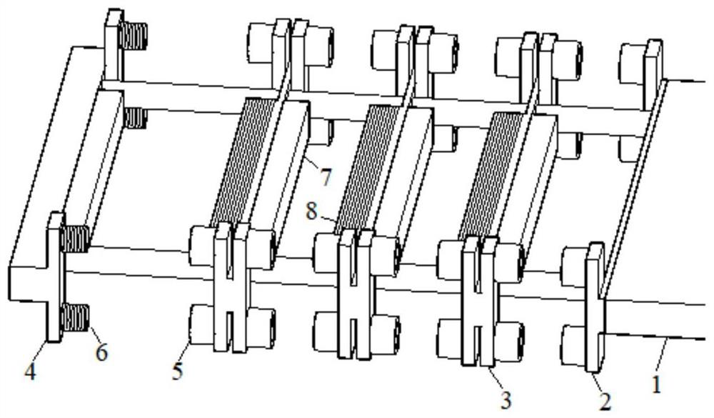
[0024] Based on the principle of conservation of momentum, the mover in high-speed motion and each deceleration unit undergoes non-contact elastic collision, and the momentum of the mover is distributed to each deceleration unit, so that the kinetic energy is transmitted layer by layer in each deceleration unit, thereby weakening the movement of the mover When the kinetic energy, to achieve the purpose of deceleration and braking. According to the mass of the mover and the final launch speed, several deceleration units are installed. The deceleration unit can be divided into the first deceleration unit, the sliding deceleration unit and the final deceleration unit. The basic skeleton of the deceleration unit is made of aluminum alloy material with high hardness. The basic skeleton of the deceleration unit of the linear motor multi-stage reducer has the same shape, and its shape is "H" shape or "one" shape.
[0025] In order to ensure the non-contact elastic collision of each ...
specific Embodiment 1
[0035] The braking method of concrete implementation example 1 is specifically as follows:
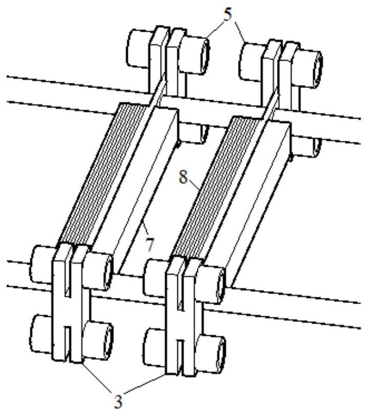
[0036] (1) The first deceleration unit 2 is fixed on the longitudinal side of the mover 1 , and the adjacent sliding deceleration unit 3 is repelled by the first deceleration unit 2 . The repelling device (5, 7, 8) on the reduction unit ensures that when the two reduction units are not in contact, the first reduction unit will move the linear induction motor mover 2 The kinetic energy is transmitted to the adjacent sliding section deceleration unit 3.
[0037] (2) The reduction unit 3 of the sliding section is installed on the mover bearing and can slide freely on the mover bearing. Transfer part of the kinetic energy of the previous deceleration unit to the next adjacent deceleration unit, and it also obtains kinetic energy, and consumes excess kinetic energy through the friction between it and the bearing and the protection resistance on several closed coils 8 on itself.
[0038] (...
Embodiment 2
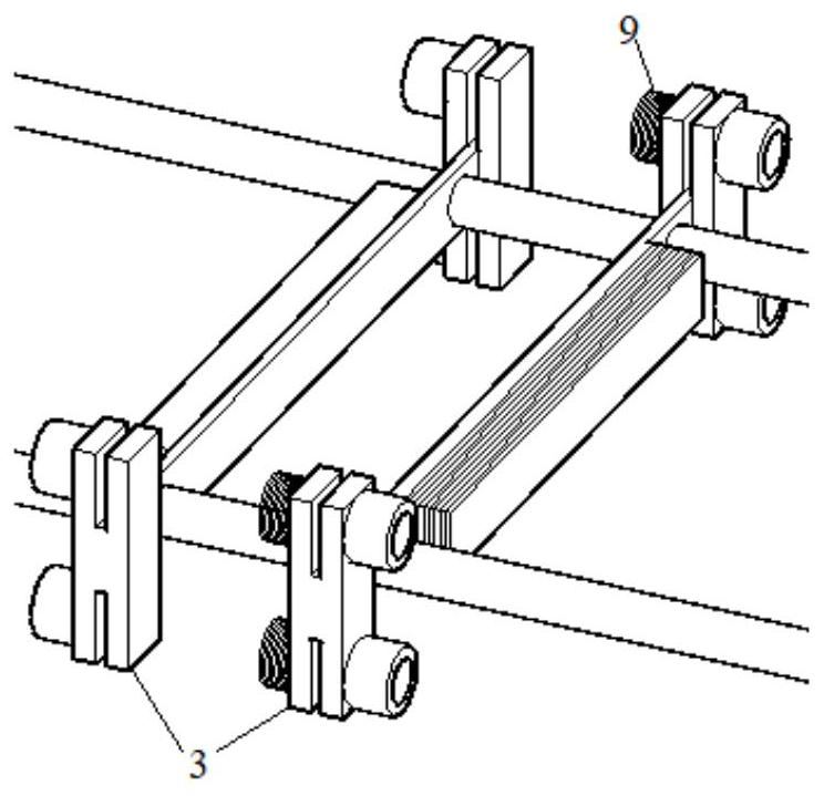
[0040] The deceleration unit of specific implementation example 2 adopts a "one" shape skeleton, and the specific implementation examples are as follows:
[0041] exist Figure 4 Among them, each deceleration unit adopts a "one"-shaped frame. Its deceleration principle is similar to that of the "H" shaped frame. Since each reduction unit can only install two secondary devices on each side, compared with the reduction unit with "H"-shaped frame, the repulsion of each reduction unit is lower, and it is only suitable for low-power linear motors. Two springs 9 are installed on the two ends on the outer side of the "one" shape skeleton on the first section deceleration unit 2. Two cylindrical neodymium-iron-boron magnets 5 are installed on the two ends on the outer side of the "one"-shaped skeleton on the sliding section deceleration unit 3. Two cylindrical electromagnets 6 are installed on the two ends on the outer side of the "one"-shaped skeleton on the final reduction unit 4...
PUM
 Abstract
Description
Claims
Application Information