
Visual inspection method and system for intelligent substation

A technology of smart substations and inspection systems, applied in the field of smart substations, can solve the problems of insufficient accuracy of inspection results and insufficient inspection efficiency, achieve a wide range of reports, improve accuracy and reliability, and improve accuracy Effect

Active Publication Date: 2020-08-14
国网江苏省电力有限公司阜宁县供电分公司
View PDF5 Cites 3 Cited by
  • Summary
  • Abstract
  • Description
  • Claims
  • Application Information

AI Technical Summary

Problems solved by technology

[0005] This application provides a visual inspection method and system for smart substations to solve the problem of insufficient accuracy of inspection results caused by inspection methods for smart substations in the prior art. The problem of insufficient inspection efficiency

Method used


Image

  • Visual inspection method and system for intelligent substation
  • Visual inspection method and system for intelligent substation
  • Visual inspection method and system for intelligent substation

Examples


Embodiment 1

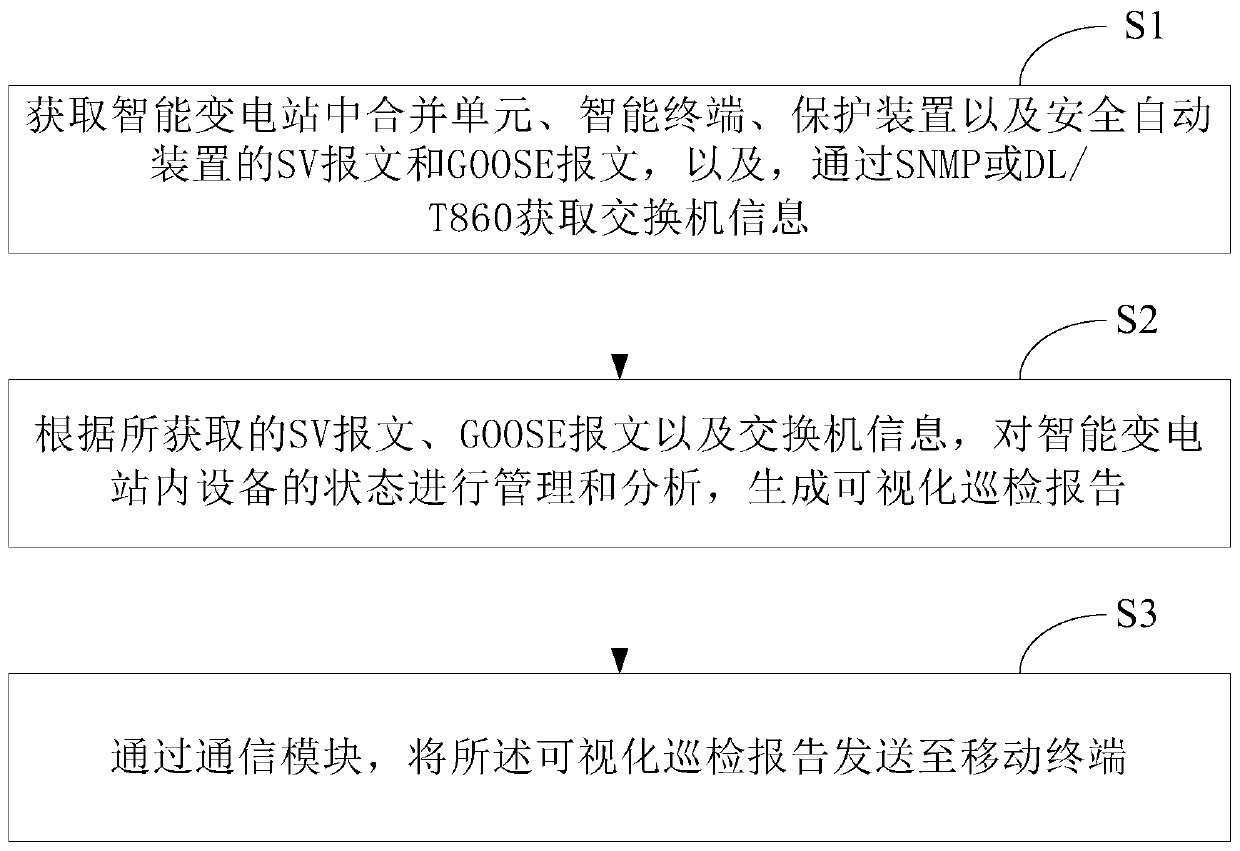
[0060] see figure 1 , figure 1 It is a schematic flowchart of a visual inspection method for a smart substation provided in the embodiment of the present application. Depend on figure 1 It can be seen that the visual inspection method for smart substations in this embodiment mainly includes the following processes:

[0061] S1: Obtain the SV message and GOOSE message of the merging unit, intelligent terminal, protection device, and safety automatic device in the smart substation, and obtain switch information through SNMP or DL / T860.

[0062] Among them, the merging unit and the intelligent terminal are set in the process layer of the smart substation, and the protection device and the safety automatic device are set in the station control layer of the smart substation. The SV message and GOOSE message data come from the process layer of the smart substation, and the fixed value and soft pressure plate check data come from the interval layer and station control layer.

[0...

Embodiment 2

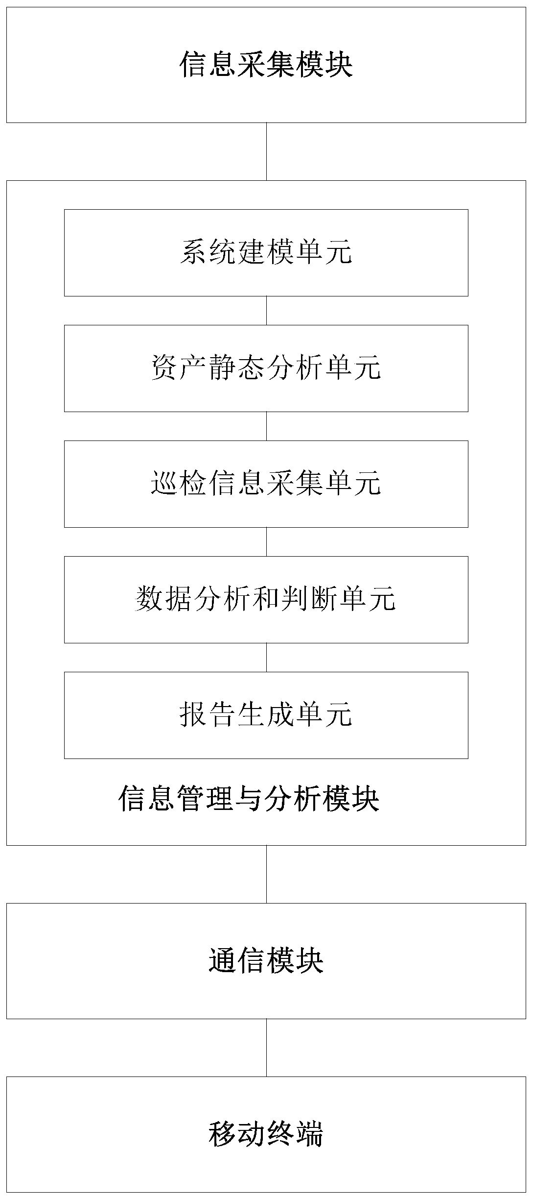
[0103] see figure 2 , figure 2 It is a schematic structural diagram of a visual inspection system for a smart substation provided by an embodiment of the present application. Depend on figure 2 It can be seen that the visual inspection system of the smart substation in this embodiment mainly includes four parts: an information collection module, an information management and analysis module, a communication module and a mobile terminal.

[0104] Among them, the information collection module is used to obtain the SV message and GOOSE message of the merging unit, intelligent terminal, protection device and safety automatic device in the smart substation, and obtain the switch information through SNMP or DL / T860, wherein the merging unit and The intelligent terminal is set in the process layer of the smart substation, and the protection device and safety automatic device are set in the compartment layer of the smart substation. The information management and analysis module...


PUM


Abstract

The invention discloses a visual inspection method and system for an intelligent substation. The method comprises the following steps: firstly, acquiring related information of equipment in a processlayer and a spacer layer in the intelligent substation, then managing and analyzing the state of the equipment in the intelligent substation according to the acquired information to generate a visualinspection report, and finally, sending the visual inspection report to a mobile terminal through a communication module. The system comprises an information acquisition module, an information management and analysis module, a communication module and a mobile terminal. According to the invention, asset management, sampling management, constant value management and inspection management of the secondary device can be realized, and finally a visual report is formed. The inspection efficiency of the intelligent substation equipment and the accuracy of the inspection result are improved.

Description

technical field [0001] The present application relates to the technical field of smart substations, in particular to a method and system for visual inspection of smart substations. Background technique [0002] With the development of the economy and the advancement of science and technology, smart substations that can adapt to sustainable development in the future are gradually replacing traditional substations. In order to ensure the normal operation of the smart substation, it is necessary to inspect the equipment of the smart substation. [0003] At present, the inspection method for smart substation equipment is usually manual inspection. That is: manual inspection of relay protection equipment, measurement and control devices, etc., and finally summarize the inspection of all equipment in the smart substation as the result of the inspection of the whole station. [0004] However, the current inspection method for smart substation equipment mainly relies on manual ins...

Claims


Application Information

Patent Timeline
IPC IPC(8): H04L12/24H04L12/26H04L29/08H02J13/00
CPCH04L41/0213H04L41/044H04L41/145H04L43/06H04L43/045H04L67/025H04L67/06H04L67/12H04L67/30H02J13/00001H02J13/00028
Inventor 胡卫丰杨浩天袁伯军耿斌黄韬唐鑫顾正松张剑飞胡明洲李衎
Owner 国网江苏省电力有限公司阜宁县供电分公司
Learn More