Ultrasonic metal pushing device

A punching device and ultrasonic technology, applied in the directions of feeding devices, positioning devices, storage devices, etc., can solve the problems of manual manual fixing of metal parts, difficult separation of metal parts and waste parts, etc., and reduce labor intensity and operation steps. The effect of reducing labor intensity and simple operation

Active Publication Date: 2020-08-18
HEZE UNIV
View PDF6 Cites 4 Cited by
  • Summary
  • Abstract
  • Description
  • Claims
  • Application Information

AI Technical Summary

Problems solved by technology

[0004] The purpose of the present invention is to provide an ultrasonic metal punching device to solve the problems that the metal parts and waste parts are difficult to separate and the metal parts need to be manually fixed in the above-mentioned background technology

Method used


Image

  • Ultrasonic metal pushing device
  • Ultrasonic metal pushing device
  • Ultrasonic metal pushing device

Examples


Embodiment 1

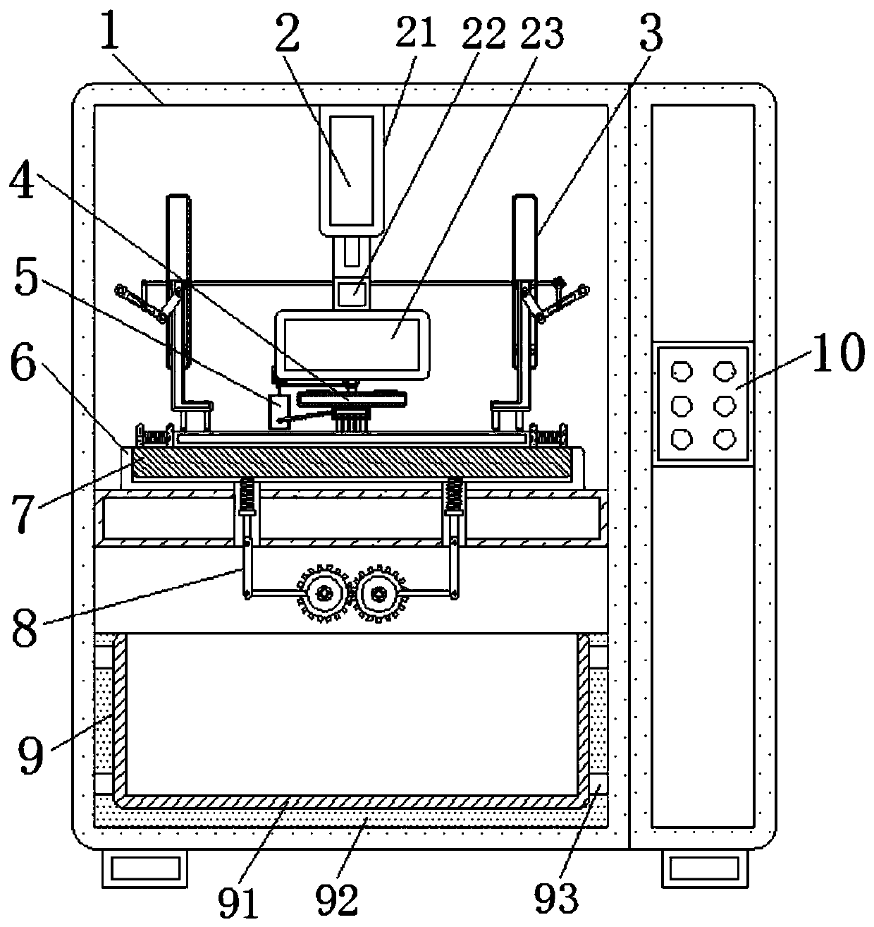
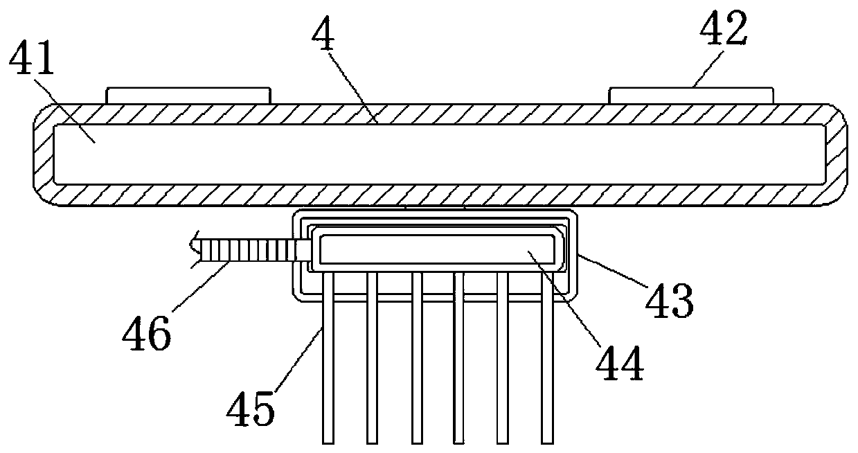
[0029]An ultrasonic metal punching device, comprising a device box 1, a punching mechanism 2 is fixedly installed at the inner center of the device box 1, and the punching mechanism 2 includes a hydraulic lifting rod 21, an ultrasonic transducer 22 and an ultrasonic punch 23. An ultrasonic transducer 22 is fixedly connected to the bottom end of the hydraulic lifting rod 21, and an ultrasonic punch 23 is installed on the bottom end of the ultrasonic transducer 22, and a separation mechanism 4 is installed on the back of the bottom end of the punching mechanism 2, and the separation mechanism 4 includes a fixed ring 41, a fixed rod 42, a sixth connecting rod 43, a telescopic rod 44, a brush 45, a hose 46, a first insertion rod 47, a fixed disc 48, a sleeve 49, a second insertion rod 410 and a limit rod 411, the surface of the fixed ring 41 is uniformly fixed with a fixed rod 42, and the bottom end of the fixed rod 42 is fixedly connected with a fixed disk 48, and the inside of th...

Embodiment 2

[0034] Embodiment 2: An ultrasonic metal punching device, including a device box 1, a punching mechanism 2 is fixedly installed at the inner center of the device box 1, and the punching mechanism 2 includes a hydraulic lifting rod 21 and an ultrasonic transducer 22 And ultrasonic punch 23, the bottom end of hydraulic lifting rod 21 is fixedly connected with ultrasonic transducer 22, and the bottom end of ultrasonic transducer 22 is equipped with ultrasonic punch 23, hydraulic lifting rod 21, ultrasonic transducer 22 and ultrasonic Punch 23 is prior art, and the bottom back of punching mechanism 2 is equipped with separating mechanism 4, and separating mechanism 4 comprises fixed ring 41, fixed rod 42, the 6th connecting rod 43, telescopic rod 44, brush 45, hose 46 , the first insertion rod 47, the fixed plate 48, the sleeve 49, the second insertion rod 410 and the limit rod 411, the surface of the fixed ring 41 is evenly fixed with the fixed rod 42, and the fixed rod 42 is prov...


PUM


Abstract

The invention discloses an ultrasonic metal pushing device which comprises a device box. A punching mechanism is fixedly mounted at the center position of the inner side of the device box, and a separating mechanism is mounted on the back face of the bottom end of the punching mechanism. The left side of the separating mechanism is connected with an air supply mechanism. Fixed mechanisms are mounted on the two sides in the device box, and the bottom ends of the fixed mechanisms are connected with a limiting mechanism. The outer side of the limiting mechanism is connected with a first limitingblock. The bottom end of the limiting mechanism is fixedly connected with a lifting mechanism, and a collection mechanism is arranged below the lifting mechanism. The fixed mechanisms and the limitingmechanism are arranged, manual fixing is not needed, it is guaranteed that the metal part punching positions are accurate, and the manual labor strength is reduced; and the air supply mechanism worksto cool the metal part punching positions, metal parts and waste parts are separated through the separating mechanism, the manual labor strength and operation steps are reduced, and operation is simple.

Description

technical field [0001] The invention relates to the technical field of ultrasonic metal punching devices, in particular to an ultrasonic metal punching device. Background technique [0002] With the continuous development of society, the metal product industry includes structural metal product manufacturing, metal tool manufacturing, container and metal packaging container manufacturing, stainless steel and similar daily metal product manufacturing, etc. With the application of metal products in various fields more and more widely , There are more and more devices for metal punching, especially ultrasonic punching devices. [0003] Existing patent number: CN201720381951.7 discloses an ultrasonic welding punching device, which includes a movable frame, an ultrasonic welding assembly, a ring mounting assembly, a punching assembly and a power assembly for driving the movable frame to reciprocate, and the ultrasonic welding assembly , the ring mounting assembly and the punching...

Claims


Application Information

Patent Timeline
Patent Type & Authority Applications(China)
IPC IPC(8): B21D28/34B21D43/00B21D37/16B21D45/02
CPCB21D28/34B21D28/002B21D43/003B21D37/16B21D45/02
Inventor 祝凤金王晓慧张俊杰高剑吕桂志付守冲江峰张东方王东峰
Owner HEZE UNIV
Why Eureka
Try Eureka