Scattered oil recovery device and method

A recovery device and oil technology, applied in packaging, transportation, packaging, containers, etc., can solve the problems of large safety hazards, safety accidents, waste of oil, etc., and achieve the effect of convenient movement, high safety, and favorable reuse

Inactive Publication Date: 2020-08-18
SHANXI LUAN COAL BASED CLEAN ENERGY
View PDF0 Cites 3 Cited by
  • Summary
  • Abstract
  • Description
  • Claims
  • Application Information

AI Technical Summary

Problems solved by technology

Due to the volatilization of the oil in the tank, the tank is often under a slight positive pressure. The top of the tank is generally connected to the flare system to deal with the flammable gas volatilized in the tank. When the gas is used, if the flammable gas is mixed with oxygen, safety accidents will easily occur. Therefore, an oxygen-free environment must be maintained in the waste oil tank, and the waste oil tank can only collect the waste oil discharged from each closed device.
[0003] In the daily production process, scattered oil materials will be discharged on-site due to necessary sampling and maintenance operations. After the scattered oil materials are discharged from the tank, on the one hand, because the waste oil tank is in a positive pressure environment, the discharged scattered oil materials cannot flow into the sewage by themselves. In the oil tank, on the other hand, the discharged scattered oil is in the air environment, and it will inevitably bring in air when directly added to the dirty oil tank, which will affect the treatment of the gas in the dirty oil tank. Therefore, for the treatment of scattered oil, collection barrels are generally installed On-site storage or direct discharge and discarding, on-site storage has great potential safety hazards, and scattered oil materials are directly discharged and discarded, resulting in waste of oil materials

Method used


Image

  • Scattered oil recovery device and method

Examples


Embodiment Construction

[0032] In order to make the object, technical solution and advantages of the present invention clearer, the present invention will be further described in detail below in conjunction with the accompanying drawings.

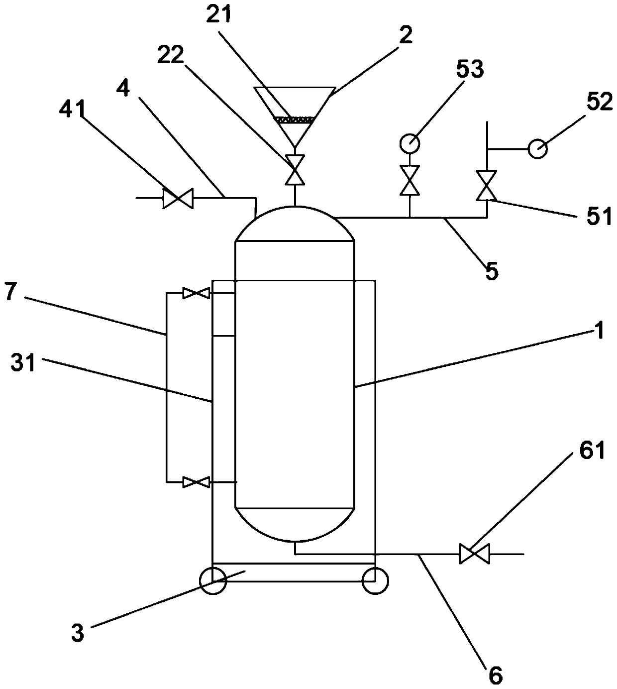
[0033] Such as figure 1 As shown, the embodiment of the scattered oil recovery device disclosed in the present invention includes a collection tank 1, a mobile platform 3, an oil discharge pipe 6, an air intake pipe 4 and an exhaust pipe 5, and the collection tank 1 is a pressure-resistant tank, and the collection tank 1 is arranged on On the mobile platform 3, the existing trolley can be selected for the mobile platform 3, the mounting frame 31 is set on the mobile platform 3, the collection tank 1 is installed on the mounting frame 31, the top of the collection tank 1 has a fuel filler, and the fuel filler is provided with a The first valve 22, the input end of the oil discharge pipe 6 communicates with the bottom of the inner cavity of the collection tank 1, th...


PUM


Abstract

The invention discloses a scattered oil recovery device. The scattered oil recovery device comprises a collecting tank, a mobile platform, an oil drain pipe, a gas inlet pipe and an exhaust pipe, wherein the collecting tank is a pressure-withstanding tank and arranged on the mobile platform, an oil filling port is formed in the top of the collecting tank, a first valve is arranged at the oil filling port, an input end of the oil drain pipe communicates with the bottom of an inner cavity of the collecting tank, a second valve is arranged on the oil drain pipe, an output end of the oil drain pipe is used for communicating with a slop tank, an input end of the gas inlet pipe is used for communicating with nitrogen supply equipment, an output end of the gas inlet pipe communicates with the topof the inner cavity of the collecting tank, a third valve is arranged on the gas inlet pipe, an input end of the exhaust pipe communicates with the top of the inner cavity of the collecting tank, anda fourth valve is arranged on the exhaust pipe. The invention further discloses a scattered oil recovery method. According to the scattered oil recovery device and method, scattered oil discharged from the tank body can be recovered to the slop tank safely, reutilization of the scattered oil is facilitated, and safety is high.

Description

technical field [0001] The invention relates to the field of oil treatment, in particular to a scattered oil recovery device and method. Background technique [0002] The waste oil tank is a commonly used waste oil treatment device in the field of industrial production. It is used for the temporary storage and collection of waste oil, which is beneficial to the recycling of waste oil. Due to the volatilization of the oil in the tank, the tank is often under a slight positive pressure. The top of the tank is generally connected to the flare system to deal with the flammable gas volatilized in the tank. When the gas is used, if the flammable gas is mixed with oxygen, safety accidents will easily occur. Therefore, an oxygen-free environment must be maintained in the waste oil tank, and the waste oil tank can only collect the waste oil discharged from each closed device. [0003] In the daily production process, scattered oil materials will be discharged on-site due to necessar...

Claims


Application Information

Patent Timeline
Patent Type & Authority Applications(China)
IPC IPC(8): B65D88/54
CPCB65D88/548
Inventor 任超苗路斌李陆山连雅申惠刘凯
Owner SHANXI LUAN COAL BASED CLEAN ENERGY
Why Eureka
Try Eureka