

A Method for Measuring Infinite High Frequency Relative Permittivity of Insulating Dielectric
A technology of relative permittivity and measurement method, which is applied in the direction of dielectric property measurement, measurement device, measurement of electrical variables, etc., can solve the problem that the relative permittivity cannot be accurately measured at infinite high frequency, etc., and achieves a simple test method and accurate results. , the effect of low cost
Active Publication Date: 2022-05-31
HARBIN UNIV OF SCI & TECH
View PDF2 Cites 0 Cited by
- Summary
- Abstract
- Description
- Claims
- Application Information
AI Technical Summary
Problems solved by technology
[0004] In order to overcome the technical problem that the infinite high frequency relative permittivity of the insulating dielectric cannot be accurately measured, the present invention proposes a method for measuring the infinite high frequency relative permittivity of the insulating dielectric, the purpose of which is to conveniently and accurately measure the infinite high frequency relative permittivity constant
Method used
View moreImage
Smart ImageViewing Examples

Examples
specific Embodiment approach 1
specific Embodiment approach 2
specific Embodiment approach 3
Login to View More PUM
| Property | Measurement | Unit |
|---|---|---|
| Area | aaaaa | aaaaa |
| Thickness | aaaaa | aaaaa |
Abstract
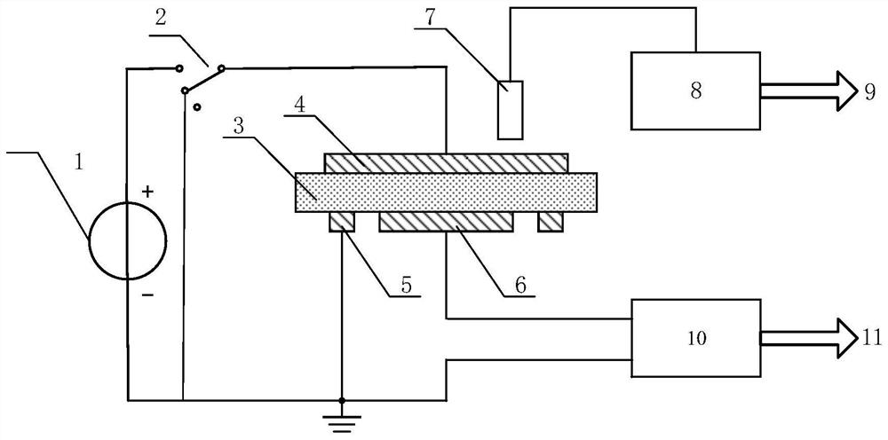
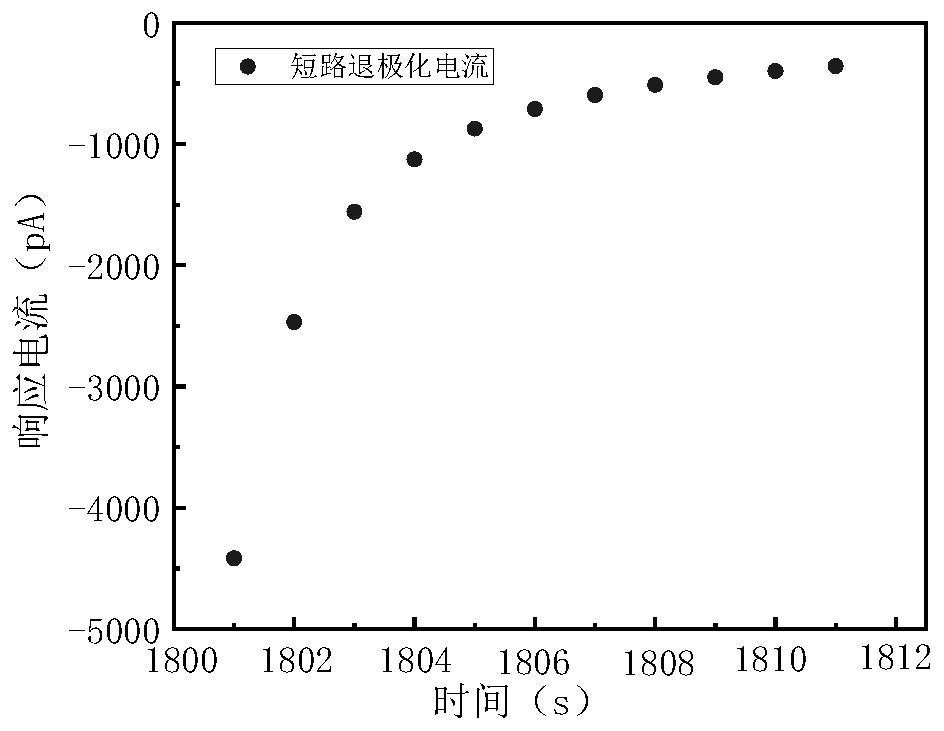
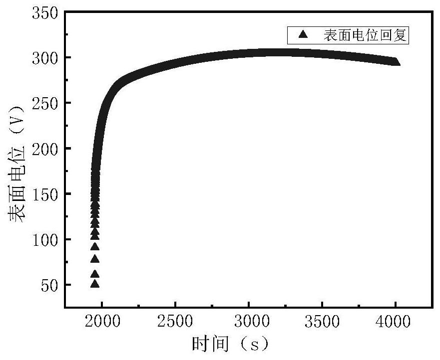
The invention discloses a measurement principle of the infinite high frequency relative permittivity of an insulating dielectric, which solves the technical problem that the infinite high frequency relative permittivity of the insulating dielectric cannot be accurately measured. The basic principle of the present invention is to use a high-voltage DC power supply to polarize the measured dielectric, and then use an acquisition system composed of an electrometer, an electrostatic voltmeter and a computer to realize the collection and recording of the short-circuit current and recovery potential time-domain spectrum of the measured insulating dielectric , through the least squares fitting to accurately obtain the initial time change rate of the recovery potential, from the initial time change rate of the recovery potential and the short-circuit current I d (t 1‑ ), through the formula to obtain the infinite high-frequency relative permittivity ε ∞ Measurement.
Description
A method for measuring the relative permittivity of insulating dielectrics at infinite high frequency technical field The present invention relates to the dielectric parameter measurement field of insulating dielectric, particularly relate to a kind of insulating dielectric infinitely high Frequency relative permittivity measurement method. Background technique [0002] Insulating dielectrics are materials that constitute the insulation of electronic devices and power equipment, and serve as electrical insulation, mechanical support and External encapsulation, etc. Relative permittivity at a given frequency (ε r ) is the expression of the action of the insulating dielectric in the electric field at a certain frequency One of the important technical indicators of low insulation performance, defined as the dielectric permittivity of the insulating medium and the vacuum permittivity at a given frequency (ε 0 ), where the vacuum dielectric constant (ε 0 ) is a...
Claims
Login to View More Application Information
Patent Timeline
 IPC IPC(8): G01R27/26
CPCG01R27/2617
Inventor索长友李忠华陈宇郭文敏郑欢韩永森孙云龙
OwnerHARBIN UNIV OF SCI & TECH