Hall sensor temperature drift compensation circuit

A Hall sensor and temperature drift technology, applied in the field of magnetic sensors, can solve problems such as large circuit differences, achieve low cost, good effect, and the effect of compensating sensitivity drift

Active Publication Date: 2020-08-18
NANJING UNIV OF POSTS & TELECOMM
View PDF5 Cites 9 Cited by
  • Summary
  • Abstract
  • Description
  • Claims
  • Application Information

AI Technical Summary

Problems solved by technology

[0004] Chinese patent CN201910456718 discloses a Hall current sensor circuit with a dual Hall element structure, but it only uses an analog circuit to p

Method used


Image

  • Hall sensor temperature drift compensation circuit
  • Hall sensor temperature drift compensation circuit
  • Hall sensor temperature drift compensation circuit

Examples


Embodiment Construction

[0025] Below in conjunction with accompanying drawing and specific embodiment, further illustrate the present invention, should be understood that these examples are only for illustrating the present invention and are not intended to limit the scope of the present invention, after having read the present invention, those skilled in the art will understand various aspects of the present invention All modifications of the valence form fall within the scope defined by the appended claims of the present application.

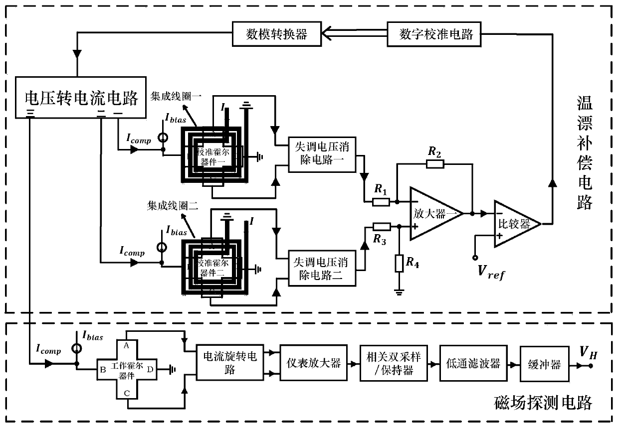
[0026] A Hall sensor temperature drift compensation circuit, such as figure 1 As shown, when the working environment temperature of the Hall sensor changes, the temperature drift of the magnetic field detection circuit of the Hall sensor is compensated in real time through the temperature drift compensation circuit, and the bias current of the Hall device is increased or decreased to Increase or decrease the Hall voltage to compensate for the temperature drift of the...


PUM


Abstract

The invention discloses a Hall sensor temperature drift compensation circuit. When the working environment temperature of the Hall sensor changes, the temperature drift of the Hall sensor is compensated in real time, and the Hall voltage is increased or decreased by increasing or decreasing the bias current of the Hall device, so that the compensation of the temperature drift of the Hall sensor isrealized. Simulation results show that the temperature drift coefficient of the compensated Hall sensor within the temperature range of-40 DEG C to 120 DEG C is 45 ppm/DEG C.

Description

technical field [0001] The invention provides a Hall sensor temperature drift compensation circuit, which belongs to the technical field of magnetic sensors. Background technique [0002] A Hall sensor is a sensor made using the Hall effect, which converts a magnetic field signal into a corresponding electrical signal. As the sensor product with the third largest demand in the world, Hall sensor is widely used in industrial control systems, automobiles and intelligent instrumentation and other fields. Due to the important role of Hall sensors in the sensor field and the huge market demand, developed countries such as the United States, Britain, Japan, and France are vigorously developing Hall sensor technology to compete for the commanding heights of Hall sensor technology. [0003] The Hall device in the Hall sensor is made of semiconductor materials. When the ambient temperature changes, its mobility and impurity concentration change, which changes the sensitivity of the ...

Claims


Application Information

Patent Timeline
IPC IPC(8): G01R33/00G01R33/07
CPCG01R33/0082G01R33/0029G01R33/07
Inventor 蒋磊徐跃宋福明
Owner NANJING UNIV OF POSTS & TELECOMM
Why Eureka
Try Eureka