

Double-loop armored optical fiber cross dense tapping structure and method
A double-circuit, connection structure technology, applied in the direction of fiber mechanical structure, light guide, optics, etc., can solve the problems of easy damage and lack of effective protection, and achieve the effect of improving protection, meeting the needs of optical fiber use, and occupying a small volume
- Summary
- Abstract
- Description
- Claims
- Application Information
AI Technical Summary
Problems solved by technology
Method used
Image

Examples
no. 1 example
[0033] The first embodiment is a double-circuit armored optical fiber cross dense branching method. The tapping method includes the following steps: Step S1 to Step S4.
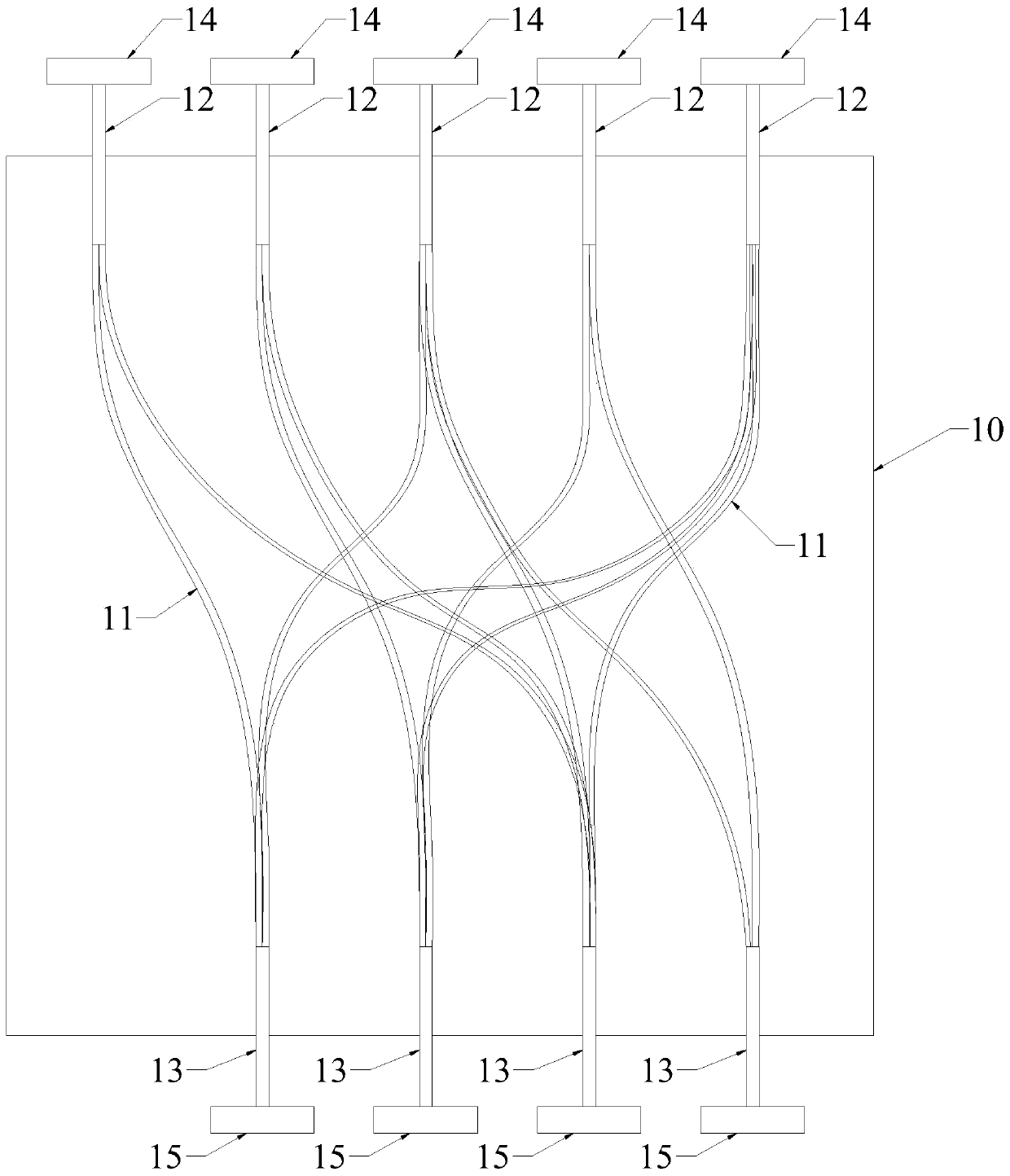
[0034] In step S1, an optical fiber wiring diagram should be designed according to the optical fiber connection function. for example, figure 1 The fiber optic wiring diagram of the first embodiment is shown, which realizes the cross-connection of 5 ports and 4 ports. In actual design, it is not limited to only follow the figure 1 Drawings for fiber optic cabling design.
[0035] In step S2, glue is coated on the prepared substrate 10 surface. The base material 10 can generally be made of PE soft rubber, and the base material 10 is a film with a relatively thin thickness (about 1 mm in thickness). The glue coated on the surface of the substrate 10 can be hot melt glue. Then, according to the optical fiber wiring diagram designed in step S1, the armored optical fiber 11 is laid on the surface of the subs...
no. 2 example
[0039] The second embodiment is a double-circuit armored optical fiber cross-dense branching structure. figure 1 It is only used to show the tapping structure of the second embodiment, and does not limit that the tapping structure must be completely in accordance with figure 1 . Such as figure 1 As shown, the tapping structure includes 5 first hubs 12 and 4 second hubs 13 . An optical fiber connector 14 is connected to the outer end of each first hub 12 . An optical fiber connector 15 is connected to the outer end of each second hub 13 . A plurality of armored optical fibers 11 that can be bent arbitrarily extend from each first hub 12 , and each second hub 13 includes a portion of armored optical fibers 11 extending from at least one first hub 12 . Such as figure 1 As shown, the tapping structure also includes a layer of substrate 10 . The armored optical fiber 11 between the first hub 12 and the second hub 13 is bonded to the substrate 10 . On the square substrate 10 ...
no. 3 example
[0041] The third embodiment is a double-circuit armored optical fiber cross-dense branching method. The tapping method includes the following steps: Step S1 to Step S4.
[0042] In step S1, an optical fiber wiring diagram should be designed according to the optical fiber connection function. for example, figure 1 The fiber optic wiring diagram of the third embodiment is shown, which realizes the cross-connection of 5 ports and 4 ports. In actual design, it is not limited to only follow the figure 1 Drawings for fiber optic cabling design.
[0043] In step S2, glue is coated on the prepared substrate 10 surface. The base material 10 can generally be made of PE soft rubber, and the base material 10 is a film with a relatively thin thickness (about 1 mm in thickness). The glue coated on the surface of the substrate 10 can be hot melt glue. Then, according to the optical fiber wiring diagram designed in step S1, the armored optical fiber 11 is laid on the surface of the subs...
PUM
 Abstract
Description
Claims
Application Information