Automatic dip-coating machine for sand core coating of brake disc

A technology of brake discs and dip coating machines, which is applied in the direction of manufacturing tools, casting molding equipment, metal processing equipment, etc., can solve problems such as waste, paint outflow, and product meat, so as to reduce production costs, avoid paint waste, and improve production efficiency effect

Inactive Publication Date: 2020-08-21
烟台美丰机械有限公司
View PDF0 Cites 0 Cited by
  • Summary
  • Abstract
  • Description
  • Claims
  • Application Information

AI Technical Summary

Problems solved by technology

[0002] With the market's increasing requirements for product appearance, normal brake disc sand cores can no longer meet customer needs, especially complex sand cores are prone to voids at the corners, resulting in meaty products and affecting product appearance quality. At present, the voids at the corners of sand cores can only It can be eliminated by manual repair or paint immersion. The efficiency of manual repair is low and the cost is high. At present, paint immersion is mostly used to solve the problem of sand core voids. Brake disc sand core coatings are manually soaked with sand cores. After soaking There will be excess paint flowing out or building up on the sand core, which is wasteful and does not achieve the desired effect

Method used


Image

  • Automatic dip-coating machine for sand core coating of brake disc
  • Automatic dip-coating machine for sand core coating of brake disc

Examples


Embodiment Construction

[0019] The principles and features of the present invention are described below in conjunction with the accompanying drawings, and the examples given are only used to explain the present invention, and are not intended to limit the scope of the present invention.

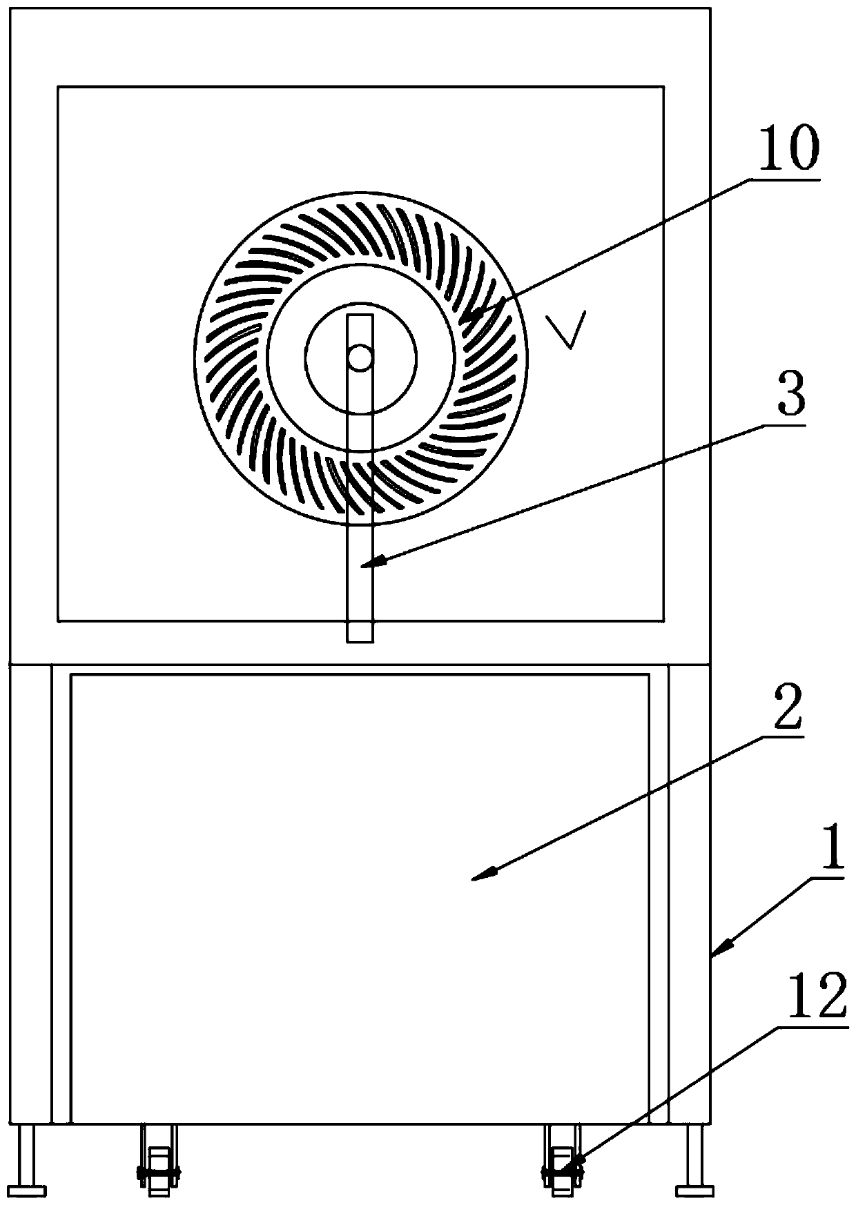
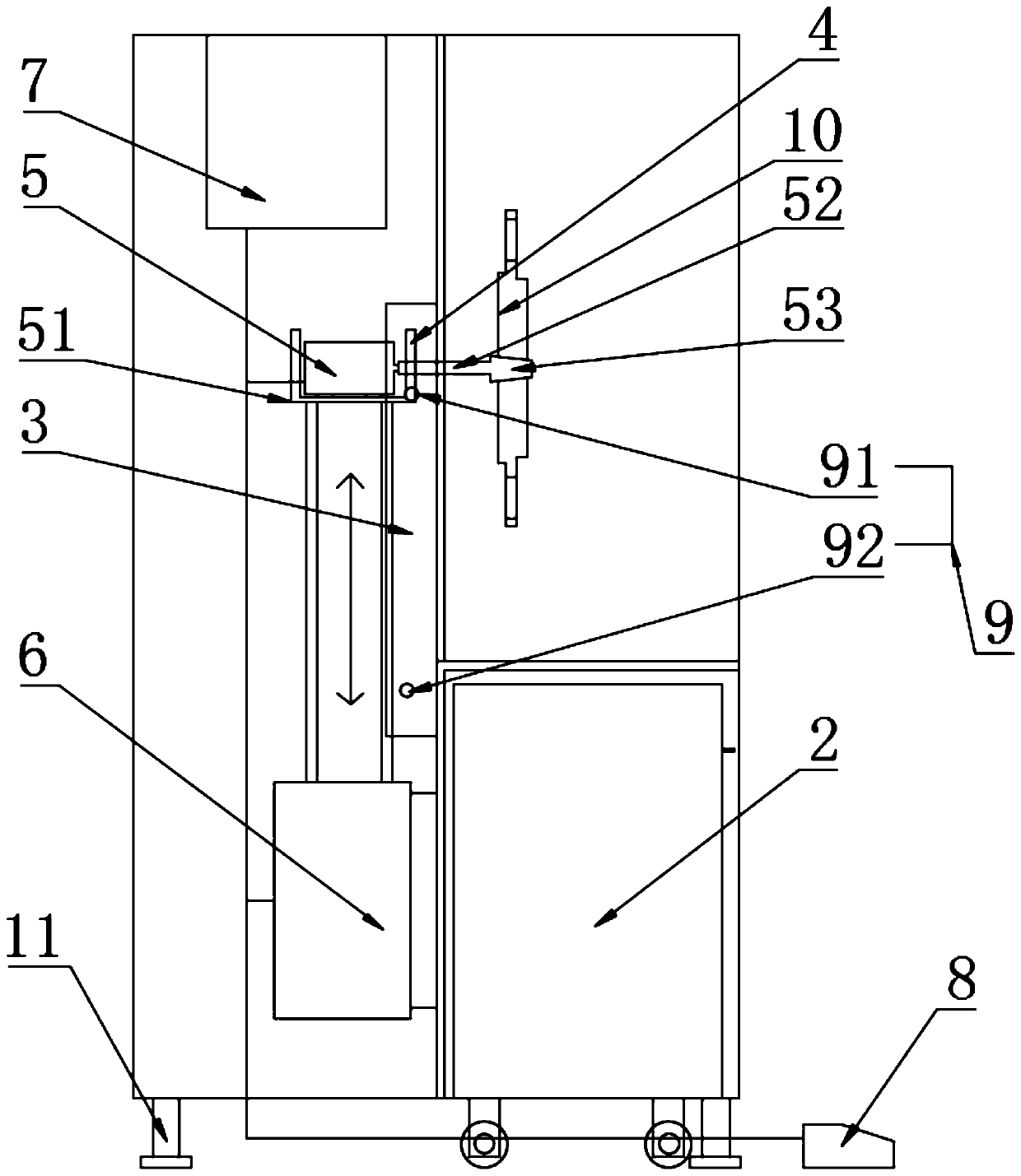
[0020] like Figure 1-Figure 2 As shown, an automatic dip coating machine for brake disc sand core paint includes a body 1, the lower end of the body 1 is provided with a fixedly connected paint tank 2 and a biaxial cylinder 6, and the biaxial cylinder 6 is located at the rear side of the paint tank 2. The cylinder 6 is provided with a fixedly connected servo motor 5, the servo motor 5 is provided with a slide block 4, the slide block 4 is provided with a slide rail 3 for sliding connection, the slide rail 3 is fixedly connected in the body 1, and the servo motor 5 The upper rotating shaft 52, one end of the rotating shaft 52 is fixedly connected with the servo motor 5, and the other end is provided with a sand core...


PUM


Abstract

The invention relates to an automatic dip-coating machine for a sand core coating of a brake disc and belongs to the technical field of sand core coatings of brake discs. The automatic dip-coating machine comprises a body, wherein a coating groove and a double shaft air cylinder fixedly connected are arranged at the lower end of the body, the double shaft air cylinder is located on the back side of the coating groove, a fixedly connected servo motor is arranged on the double shaft air cylinder, a slide block is arranged on the servo motor, a slidably connected slide rail is arranged on the slide block, the slide rail is fixedly connected in the body, a rotating shaft is arranged on the servo motor, one end of the rotating shaft is fixedly connected to the servo motor while the other end ofthe rotating shaft is provided with a sand core connector, and the sand core connector is located above the coating groove. A position needed to brush the coating of the sand core of the brake disc is dipped as the servo motor rotates a t a low speed, the depth of the sand core entering the coating groove is adjusted by a limiting switch, the dipping time is controlled by a timer, and the coatingflows into a material pond through an equipment protecting hood to recycle, so that the labor intensity of workers is reduced, waste of the coating is avoided, the production cost is lowered, the production efficiency is improved, and meanwhile, the product quality is ensured.

Description

technical field [0001] The invention relates to an automatic dip coating machine for brake disc sand core paint, which belongs to the technical field of brake disc sand core paint. Background technique [0002] With the market's increasing requirements for product appearance, normal brake disc sand cores can no longer meet customer needs, especially complex sand cores are prone to voids at the corners, resulting in meaty products and affecting product appearance quality. At present, the voids at the corners of sand cores can only It can be eliminated by manual repair or paint immersion. The efficiency of manual repair is low and the cost is high. At present, paint immersion is mostly used to solve the problem of sand core voids. Brake disc sand core coatings are manually soaked with sand cores. After soaking Excess paint will run off or build up on the core, which is wasteful and unintended. Contents of the invention [0003] The present invention aims at the deficiencies...

Claims


Application Information

Patent Timeline
IPC IPC(8): B22C23/02
CPCB22C23/02
Inventor 孙国辉王勇杨永明刘京涛
Owner 烟台美丰机械有限公司
Why Eureka
Try Eureka