
Testing method and system of combined heat and power generation unit running area

A technology for cogeneration units and operating areas, applied in the field of electric power, can solve problems such as the inability to effectively dispatch the grid power of the units, and achieve the effect of avoiding economic losses

Active Publication Date: 2020-08-21
ELECTRIC POWER RES INST OF GUANGXI POWER GRID CO LTD
View PDF5 Cites 7 Cited by
  • Summary
  • Abstract
  • Description
  • Claims
  • Application Information

AI Technical Summary

Problems solved by technology

[0003]The purpose of this invention is to overcome the deficiencies of the prior art. According to the heat supply flow, it is necessary to effectively schedule the grid-connected electric power of the unit, which not only guarantees the heat supply test demand of the unit, but also fully exerts the power peak-shaving capability of the unit, and enhances the flexibility of real-time adjustment of heat supply and electric power of the generator set after transformation.

Method used


Image

  • Testing method and system of combined heat and power generation unit running area
  • Testing method and system of combined heat and power generation unit running area
  • Testing method and system of combined heat and power generation unit running area

Examples


Embodiment Construction

[0033] The following will clearly and completely describe the technical solutions in the embodiments of the present invention with reference to the accompanying drawings in the embodiments of the present invention. Obviously, the described embodiments are only some, not all, embodiments of the present invention. Based on the embodiments of the present invention, all other embodiments obtained by persons of ordinary skill in the art without creative efforts fall within the protection scope of the present invention.

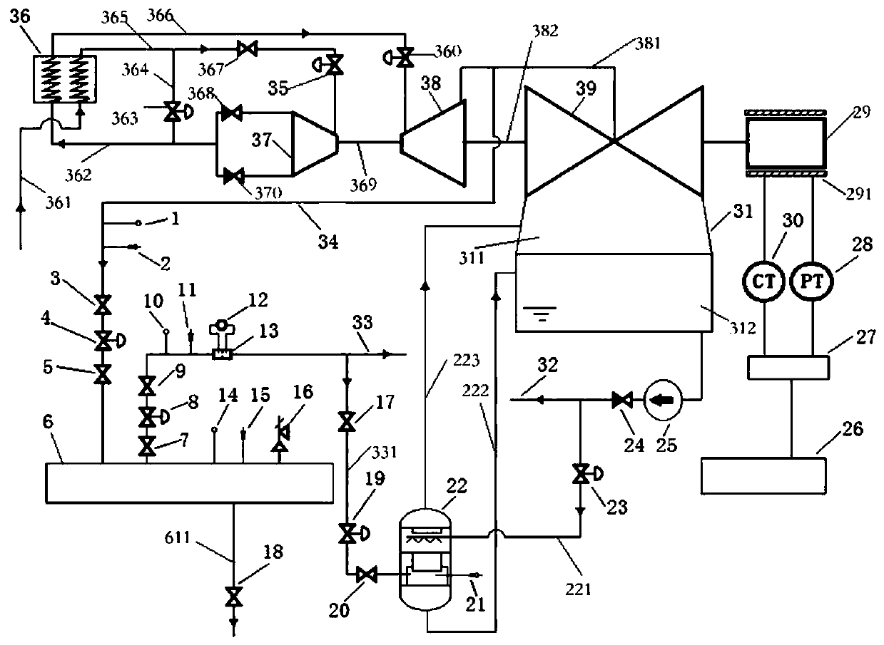
[0034] specific, figure 1 It shows a schematic structural diagram of the test system for the operation area of ​​the cogeneration unit in the embodiment of the present invention, and the cogeneration unit includes: a boiler 36, a steam turbine high-pressure cylinder 37, a steam turbine medium-pressure cylinder 38, a steam turbine low-pressure cylinder 39, and a generator set 29 , condenser 31, generator set electric power tester 27, heating steam header 6 and steam...


PUM


Abstract

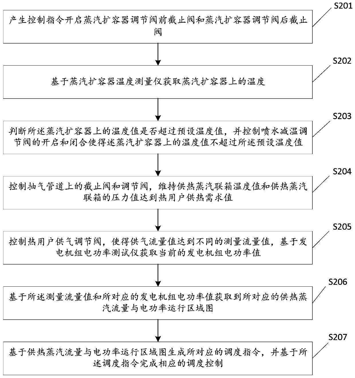
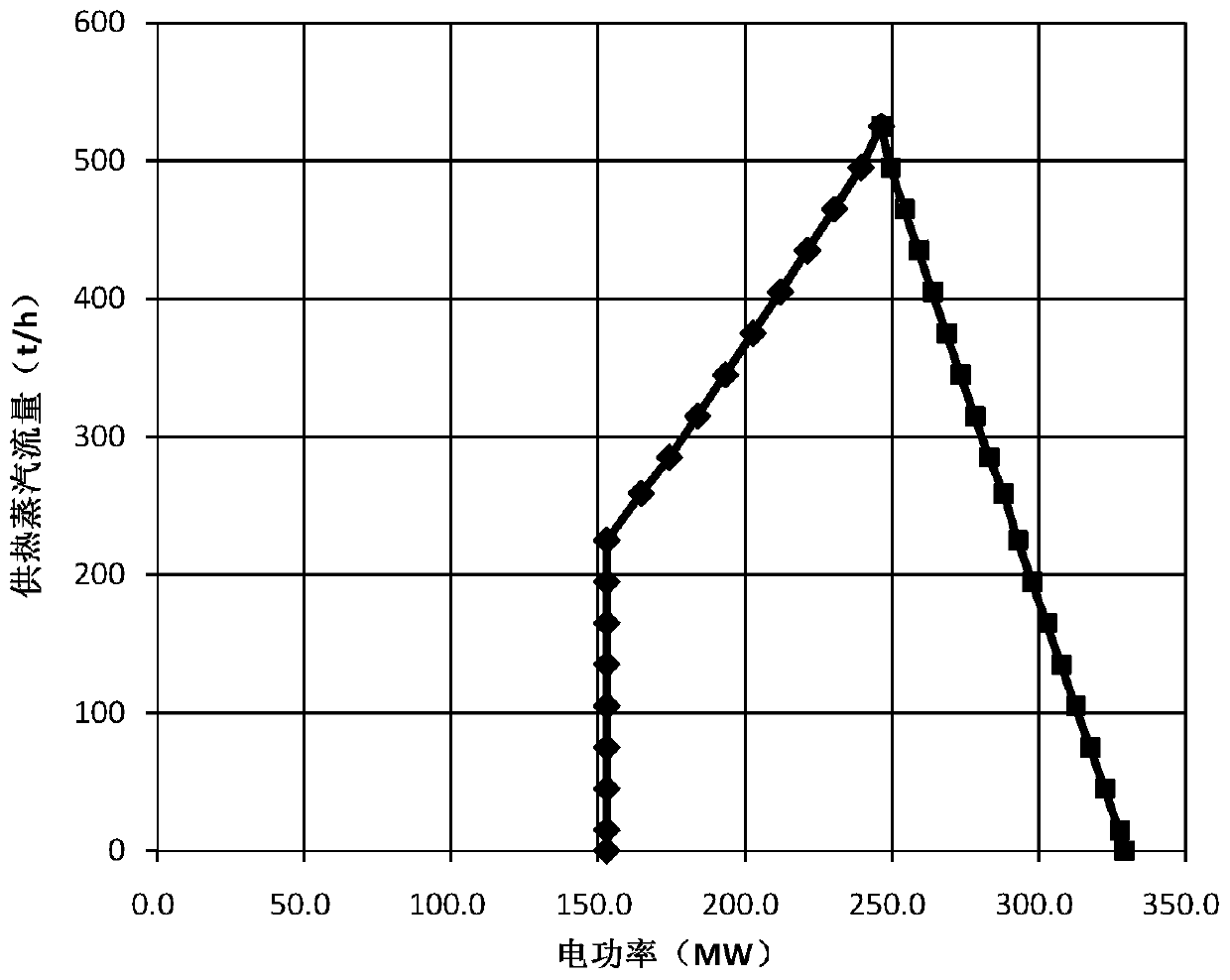
The invention discloses a testing method and system of a combined heat and power generation unit running area. The method includes the following steps that a control command is generated to open a steam expanding vessel adjusting valve front stop valve and a steam expanding vessel adjusting valve back stop valve; the temperature of a steam expanding vessel is acquired on the basis of a steam expanding vessel temperature measurement instrument; a stop valve and an adjusting valve on an exhaust pipeline are controlled, the temperature value and the pressure value of a heating steam header are maintained to reach the heat user heating requirement values; a heat user gas supply adjusting valve is controlled, so that the gas supply flow value reaches different measured flow values, and the current power generation unit electric power value is acquired on the basis of a power generation unit electric power testing instrument; and the corresponding heating steam flow and electric power running area chart is acquired on the basis of the measured flow value and the corresponding power generation unit electric power value. According to the method and the system, the unit heating requirementis guaranteed, meanwhile, the unit electric power peak adjustment capacity is fully exerted, and the heating and electric power real-time adjustment flexibility of the transformed power generation unit is enhanced.

Description

technical field [0001] The invention relates to the field of electric power technology, in particular to a method and system for testing the operating area of ​​a cogeneration unit. Background technique [0002] In response to the requirements of the national energy conservation and environmental protection policy, small industrial boilers have been gradually eliminated and replaced by the transformation of the surrounding condensing steam generating units to realize the supply of steam to heat consuming enterprises through steam extraction. There are problems such as complicated process, large engineering quantity and long time for drilling steam extraction from the steam turbine body. The method of drilling steam extraction from the medium-pressure cylinder communication pipe and high-pressure cylinder exhaust pipe (that is, the cold section of the reheater) of the steam turbine is widely used. The steam extraction heating supply of the medium-pressure cylinder Unicom pipe...

Claims


Application Information

Patent Timeline
Patent Type & Authority Applications(China)
IPC IPC(8): F01D15/10F01D17/10F01K11/02F22B37/02F22B37/38F22B37/54F22B35/00F22D11/06F22G5/12F24D1/00G01R21/00G01R19/00
CPCF01D15/10F01D17/10F01K11/02F22B37/02F22B37/38F22B35/00F22G5/123F22D11/06F22B37/54F24D1/00G01R21/00G01R19/00Y02E20/14
Inventor 文立斌
Owner ELECTRIC POWER RES INST OF GUANGXI POWER GRID CO LTD
Learn More