
Electric power copper material machining method

A processing method and technology of copper materials, applied in the direction of charge manipulation, charge composition/state, lighting and heating equipment, etc., can solve the problems of time-consuming and laborious, low safety factor of manual delivery, etc., to improve production efficiency, reduce labor cost input, The effect of increasing the speed of input

Inactive Publication Date: 2020-08-21
JIANGSU HENGTONG ELECTRICAL SPECIAL WIRE CO LTD
View PDF2 Cites 0 Cited by
  • Summary
  • Abstract
  • Description
  • Claims
  • Application Information

AI Technical Summary

Problems solved by technology

[0003] The purpose of the present invention is to provide a copper material processing method used in electric power, which can not only solve the time-consuming and labor-intensive problem of manual delivery of copper plates in the prior art, but also solve the problem of low safety factor of manual delivery

Method used


Image

  • Electric power copper material machining method
  • Electric power copper material machining method

Examples


Embodiment 1

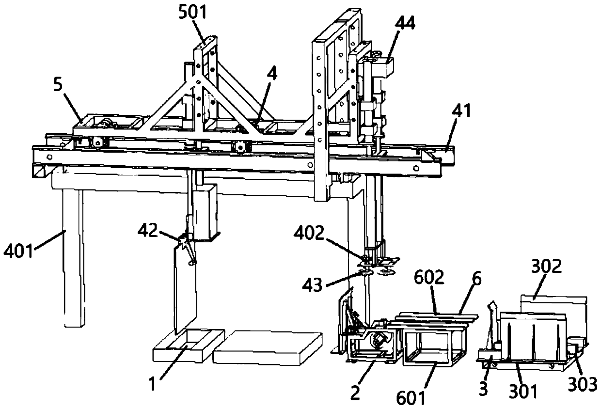
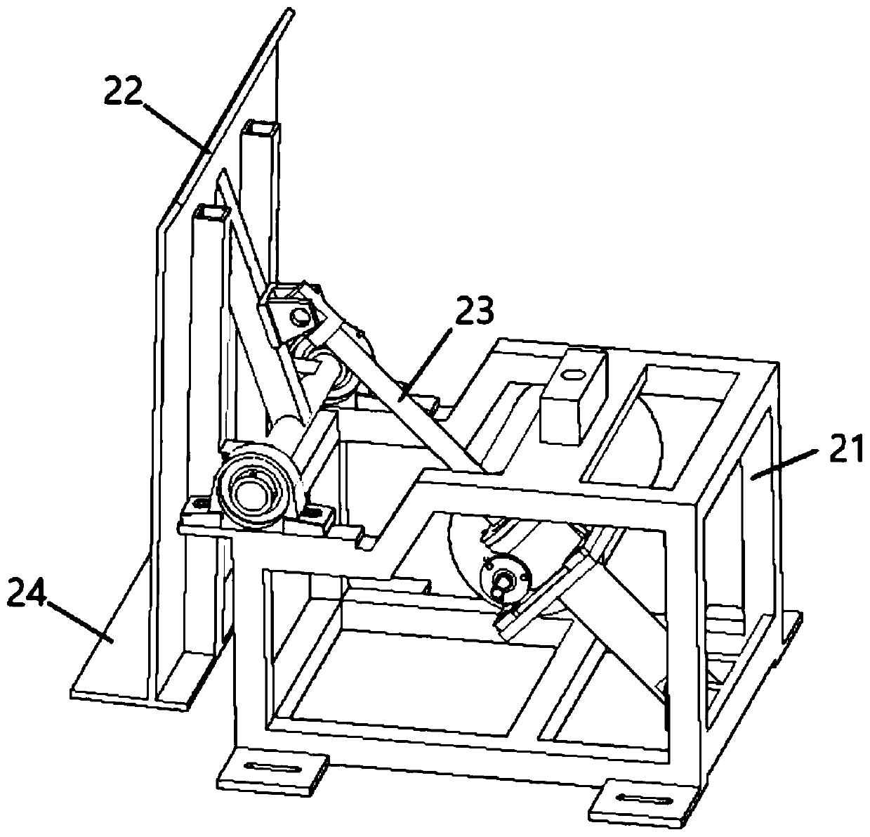
[0023] Embodiment 1: A copper material processing method used in electric power, with reference to the accompanying drawings, the copper material processing method is based on a specific device, which includes a turning mechanism 2 installed on one side of the furnace mouth 1, a storage rack 3 and Transport mechanism 4, the storage rack 3 is used to stack copper plates, the turning mechanism 2 is installed between the storage rack 3 and the furnace mouth 1, and the turning mechanism 2 further includes a turning frame 21, a turning plate 22 and a telescopic rod 23, one end of the flap 22 close to the furnace mouth 1 is hinged on the flip frame 21, the other end of the flap 22 is hinged to one end of the telescopic rod 23, and the other end of the telescopic rod 23 is hinged to the bottom of the flip frame 21, the flap A baffle plate 24 is installed on the top surface of 22, and this baffle plate 24 is located on the side of the turnover plate 22 close to the furnace mouth 1;

...

Embodiment 2

[0030] Embodiment 2: A copper material processing method used in electric power, with reference to the accompanying drawings, the copper material processing method is based on a specific device, which includes a turning mechanism 2 installed on one side of the furnace mouth 1, a storage rack 3 and Transport mechanism 4, the storage rack 3 is used to stack copper plates, the turning mechanism 2 is installed between the storage rack 3 and the furnace mouth 1, and the turning mechanism 2 further includes a turning frame 21, a turning plate 22 and a telescopic rod 23, one end of the flap 22 close to the furnace mouth 1 is hinged on the flip frame 21, the other end of the flap 22 is hinged to one end of the telescopic rod 23, and the other end of the telescopic rod 23 is hinged to the bottom of the flip frame 21, the flap A baffle plate 24 is installed on the top surface of 22, and this baffle plate 24 is located on the side of the turnover plate 22 close to the furnace mouth 1;

...


PUM


Abstract

The invention discloses an electric power copper material machining method. The method comprises the following steps that S1, electric hoists provided with suction cups are driven to move on guide rails to the upper portion of a material storage frame, the electric hoists drive the suction cups to move downwards to suck a horizontally-placed copper plate, and the copper plate is transported onto aturnover plate of a turnover mechanism; S2, after the suction cups are separated from the copper plate on the turnover mechanism, a telescopic rod pushes the turnover plate to rotate, and thus, the copper plate on the turnover plate is rotated to a vertical state; S3, the two electric hoists are symmetrically driven to move on the guide rails to the upper portions of the material storage frame and the turnover mechanism correspondingly, the electric hoists drive the suction cups and a clamping jaw to move downwards, the suction cups suck the copper plate on the material storage frame again, and the clamping jaw camps the copper plate which is in a vertical state on the turnover plate; S4, the suction cups sucking the copper plate move to the turnover mechanism to place down the copper plate, and the clamping jaw synchronously moves to the upper portion of a furnace mouth to charge the copper plate; and S5, the steps of S2, S3 and S4 are repeated. The invention achieves full automaticcharging of copper plates, and the charging efficiency and safety coefficient of the copper plates are improved.

Description

technical field [0001] The invention relates to a method for processing copper materials used in electric power, and belongs to the technical field of electric power cable processing. Background technique [0002] The copper smelting process in power cables is essential, and the feeding of the smelting furnace is one of the key operations affecting the smelting process. At present, in the production process of secondary copper smelting and processing enterprises, metallurgical furnace materials are generally fed manually or by mobile machinery. However, due to the large volume of the melting furnace, high working temperature, and large feeding volume, the traditional feeding has problems such as low production efficiency, high labor intensity, harsh working environment, and serious pollution. Moreover, with the shortage of labor force and the increase of wage level, the cost of labor is constantly increasing. It is an urgent problem for domestic smelters to replace manual o...

Claims


Application Information

Patent Timeline
Patent Type & Authority Applications(China)
IPC IPC(8): F27D3/00C22B15/00
CPCC22B15/0028F27D3/0025F27D2003/0069F27M2001/015F27M2003/13
Inventor 孙卿卿沈建新宋健磊孙福林金榕
Owner JIANGSU HENGTONG ELECTRICAL SPECIAL WIRE CO LTD
Learn More