Universal radio radar, target signal simulator and using method thereof

A target signal, radio technology, applied in the direction of radio wave measurement systems, instruments, etc., can solve the problems of different technical indicators, poor maintainability and versatility, and poor producibility and versatility.

Active Publication Date: 2020-08-21
SHANGHAI RADIO EQUIP RES INST
View PDF8 Cites 2 Cited by
  • Summary
  • Abstract
  • Description
  • Claims
  • Application Information

AI Technical Summary

Problems solved by technology

[0004] The first method is to design a simulator according to the technical requirements of a certain type of radio homing device for radio radar and target signal simulators. In the design plan, except that the radio frequency reference module uses a standard high-frequency signal source, the rest of the design uses non-standard dedicated The biggest feature of circuit design is strong specificity, but there are also problems such as long circuit design cycle, poor productivity, scalability, versatility and maintainability.
[0005] The second method is to design a simulator according to the technical requirements of a certain type of radio homing device for radio radar and target signal simulators. In the design plan, except that the radio frequency reference module uses a standard high-frequency signal source and the control combination uses an industrial computer, the rest Some still use non-standard special circuit design. Compared with the first method, this method improves the versatility, scalability and standardization of the control combination, but the video combination and radio frequency combination still have a long circuit design cycle, Issues of poor

Method used


Image

  • Universal radio radar, target signal simulator and using method thereof
  • Universal radio radar, target signal simulator and using method thereof
  • Universal radio radar, target signal simulator and using method thereof

Examples


Embodiment Construction

[0066] The present invention will be further elaborated below by describing a preferred specific embodiment in detail in conjunction with the accompanying drawings.

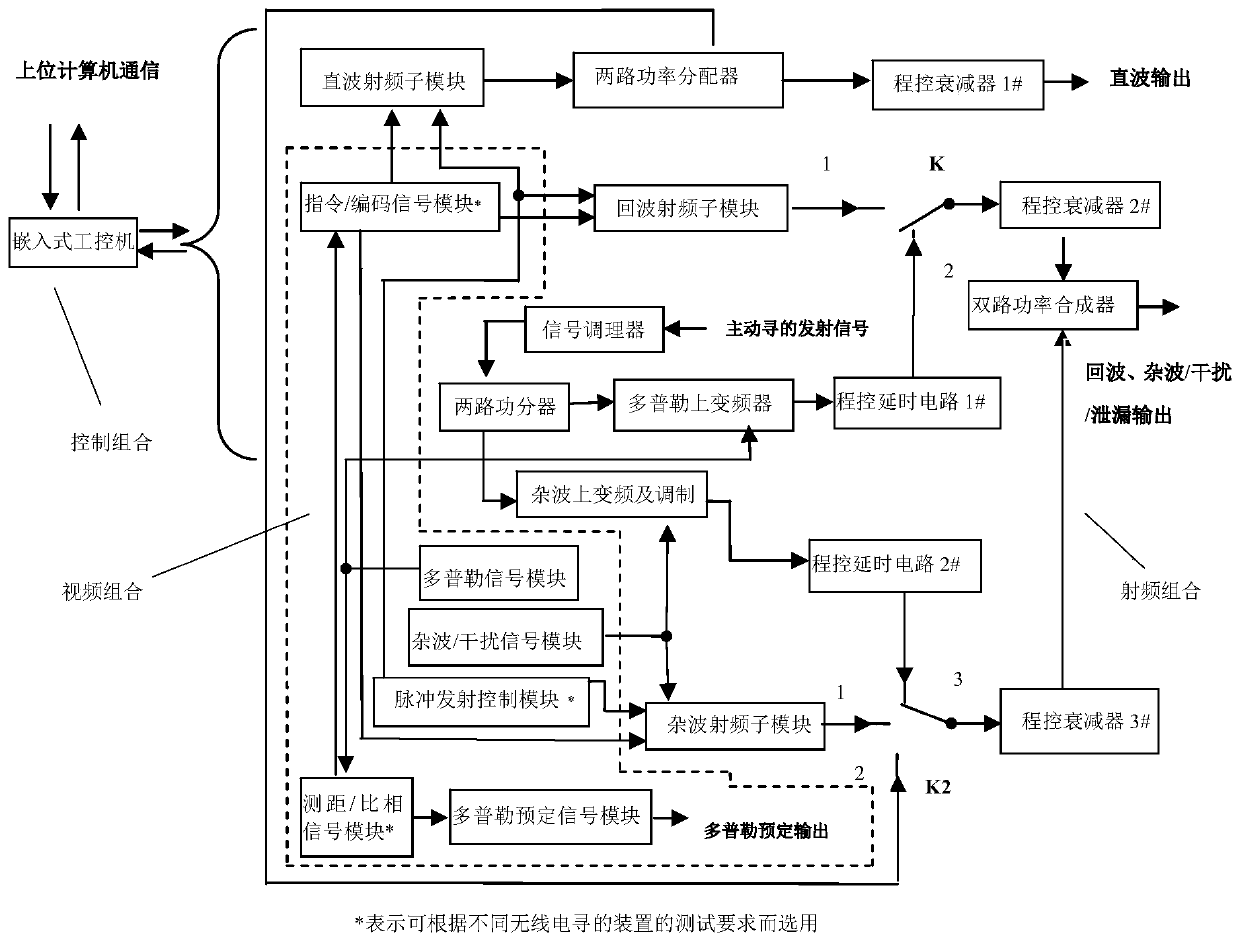
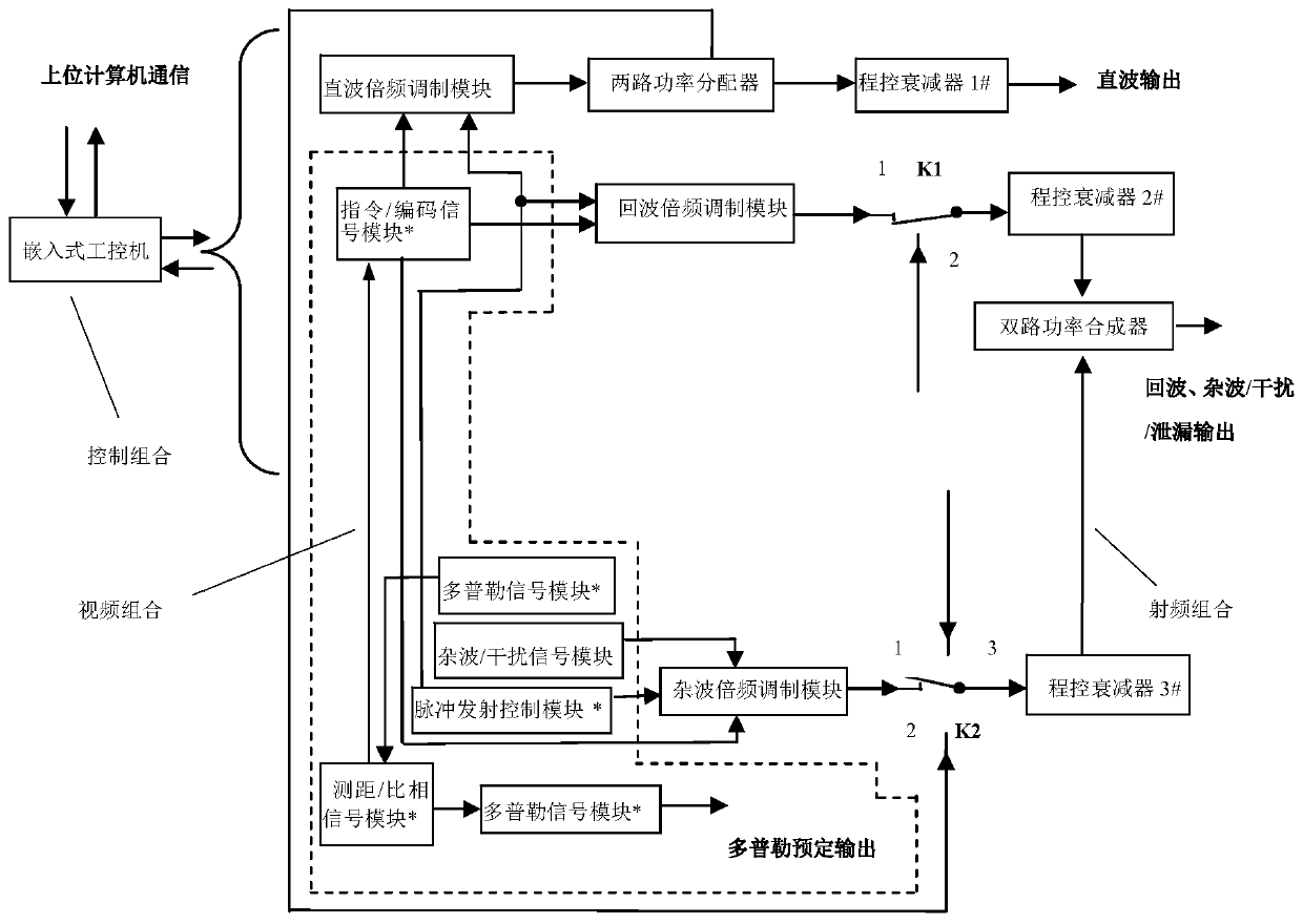
[0067] Such as figure 1 Shown is a general radio radar and target signal simulator of the present invention, the simulator includes: radio frequency combination, video combination and control combination.

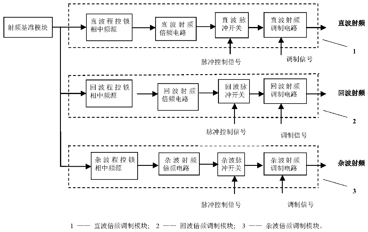
[0068] The radio frequency combination is used to generate (irradiation) direct wave, echo and clutter three-way analog carrier frequency signals of different radio homing devices; the video combination is used to generate video signals required for testing different radio homing devices, so that the The carrier frequency signal in the radio frequency combination is modulated to generate three analog radio frequency signals of direct wave, echo and clutter; the control combination receives analog control instructions through man-machine dialogue or from the host computer, and the control combination controls t...


PUM


Abstract

The invention provides a universal radio radar and target signal simulator and a using method thereof. The simulator is composed of three parts of video combination, radio frequency combination and control combination. The radio frequency combination part is used for generating three paths of carrier frequency signals of irradiation straight waves, echo waves and clutters for simulating differentradio homing devices; the video combination part is used for generating analog video signals of different wireless homing devices, and modulating the video signals to carrier frequency signals to generate three paths of radio frequency signals of analog irradiation straight waves, echoes and clutters; the control combination part controls the radio frequency combination part and the video combination part to generate signals of corresponding parameters and modulation characteristics between the signals through man-machine conversation or by receiving an analog control instruction from an uppercomputer. The simulator has the advantages that the combination mode in the video combination, the radio frequency combination and the control combination is optimized, so that the simulator can meetthe simulation requirements of radars and target signals of radio homing devices with various homing modes and various models.

Description

technical field [0001] The present invention relates to the technical field of radio radar and target signal simulation, in particular to a simulation device and a method for designing and using a radio homing device capable of simulating multiple homing modes on an aircraft on the ground in the air. Radar and target signal simulator and usage method. Background technique [0002] The radio radar and target signal simulator is a main equipment for ground simulation testing of the homing capability of the radio homing device on the aircraft by simulating radio radar and target signals. The homing methods of the radio homing device of the aircraft mainly include three types: active homing, semi-active homing and passive homing. The analog signals are mainly divided into three categories: direct wave (irradiation wave), echo, and clutter / interference. The direct wave signal is the radio frequency signal of the radar irradiating the target; the echo signal is the target reflect...

Claims


Application Information

Patent Timeline
IPC IPC(8): G01S7/40
CPCG01S7/4052
Inventor 方革非易宇李妙余李盘虎黄凯李森楼德雄
Owner SHANGHAI RADIO EQUIP RES INST
Why Eureka
Try Eureka