Underneath type arc extinguishing structure of small-sized sealed electromagnetic relay bottom plate

A technology for sealing electromagnetic and relays, which is applied in the direction of electromagnetic relays, electromagnetic relay details, relays, etc., can solve problems such as the influence of relay pull-in and release performance, accelerated relay life loss, and poor contact reliability, etc., to achieve improved Life and overload resistance, arc elimination, and the effect of reducing ablation

Active Publication Date: 2020-08-21
HARBIN INST OF TECH
View PDF14 Cites 0 Cited by
  • Summary
  • Abstract
  • Description
  • Claims
  • Application Information

AI Technical Summary

Problems solved by technology

In small sealed electromagnetic relays, contact bonding is the most common fault form. Due to the small internal space of the relay, it is difficult to set up the arc extinguishing device. The arc can easily cause ablation or even welding of the contacts, resulting in poor contact reliability of the contacts
At the same time, the heat flow generated by continuous arcing makes the contact area appear higher temperature, and a large amount of heat will spread to other components along with the arc spray, which will cause the performance of the electromagnetic system to decline, affect the pull-in and release performance of the relay, and accelerate the life loss of the relay

Method used


Image

  • Underneath type arc extinguishing structure of small-sized sealed electromagnetic relay bottom plate
  • Underneath type arc extinguishing structure of small-sized sealed electromagnetic relay bottom plate
  • Underneath type arc extinguishing structure of small-sized sealed electromagnetic relay bottom plate

Examples


specific Embodiment approach 1

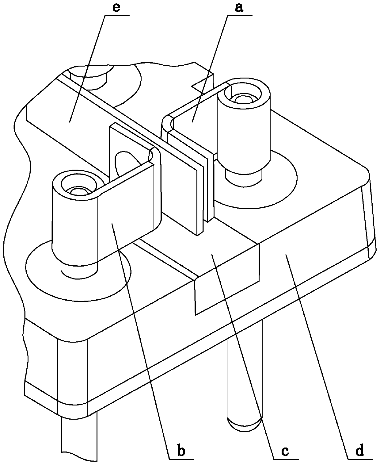
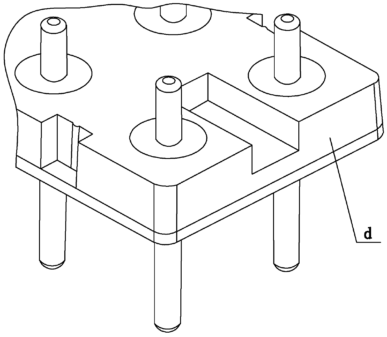
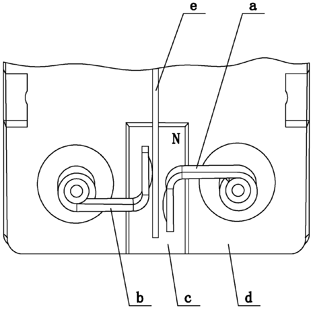
[0016] Specific implementation mode one: as figure 1 , figure 2 As shown, this embodiment discloses a small-sized sealed electromagnetic relay bottom plate arc extinguishing structure, including a permanent magnet c and a contact spring group; the contact spring group is vertically arranged on the upper surface of the bottom plate d of the electromagnetic relay, and the curled end of the contact spring group It is welded and fixed on the lead-out rod, and the lead-out rod and the glass insulator are sintered and fixed on the bottom plate d; one end of the upper surface of the bottom plate d is provided with a long groove, and the permanent magnet c is embedded in the long groove and fixed by glue (permanent The magnet c needs to be magnetized and stabilized before being embedded in the long slot), and the upper surface of the permanent magnet c is flush with the upper surface of the bottom plate d (so that the permanent magnet c can be stably fixed in the long slot, and it is...


PUM


Abstract

The utility model discloses an underneath type arc extinguishing structure of a small-sized sealed electromagnetic relay base plate, belonging to the technical field of electromagnetic relays. The underneath type arc extinguishing structure of the small-sized sealed electromagnetic relay bottom plate comprises a permanent magnet and a contact spring group, the contact spring group is vertically arranged on the upper surface of the base plate of an electromagnetic relay; a long groove is formed in one end of the upper surface of the base plate, the permanent magnet is embedded into the long groove and fixed in a glued mode, the upper surface of the permanent magnet is flush with the upper surface of the base plate, the contact spring group is arranged on the upper surface of the permanent magnet, a permanent magnetic field of the permanent magnet is perpendicular to contact gaps of the contact spring group, and the sheet ends of the contact spring set extend in the same direction or opposite directions. When the electromagnetic relay acts, electric arcs generated between contacts are lengthened under the effect of the magnetic field so as to be quickly extinguished, damage of electric arc ablation to the surfaces of the contacts is reduced, meanwhile, quick diffusion of electric arc heat is facilitated, influence of heat generated by continuous arcing on an electromagnetic system is reduced, the service life of the relay is prolonged, and the overload resistance is improved.

Description

technical field [0001] The invention belongs to the technical field of electromagnetic relays, and in particular relates to an arc extinguishing structure with a bottom plate of a small sealed electromagnetic relay. Background technique [0002] Small sealed electromagnetic relays are widely used in aviation, aerospace, communication and other fields, and play key roles in signal transmission and circuit switching. In small sealed electromagnetic relays, contact bonding is the most common fault form. Due to the small internal space of the relay, it is difficult to set up the arc extinguishing device. The arc can easily cause ablation or even welding of the contacts, resulting in poor contact reliability of the contacts. At the same time, the heat flow generated by continuous arcing makes the contact area appear higher temperature, and a large amount of heat will spread to other components along with the arc jet, which will cause the performance of the electromagnetic system...

Claims


Application Information

Patent Timeline
Patent Type & Authority Applications(China)
IPC IPC(8): H01H50/38H01H50/56
CPCH01H50/38H01H50/56
Inventor 李博梁慧敏张家赫富嘉城谭旭
Owner HARBIN INST OF TECH
Why Eureka
Try Eureka