Electronic blind guide instrument based on machine vision

A machine vision and electronic technology, applied in the direction of instruments, computer parts, and appliances that help people walk, can solve the problems of low penetration rate, short detection distance of sensors, high price, etc., to ensure the recognition quality and good universality , easily affordable effect

Pending Publication Date: 2020-08-25
DALIAN NATIONALITIES UNIVERSITY
View PDF0 Cites 0 Cited by
  • Summary
  • Abstract
  • Description
  • Claims
  • Application Information

AI Technical Summary

Problems solved by technology

[0003] Due to the large detection range of the ultrasonic sensor, it can only judge whether there are obstacles in the range, which makes the user only judge whether there are obstacles in the general direction and cannot know the specific location, which cannot be of great help to practical applications.
The infrared sensor is divided into two categories, one is a range sensor, such as the near field to determine whether there is an object, the detection distance of this type of sensor is too short; the other type of laser sensor, through the beam reflection to determine whether there is an obstacle, its disadvantages The detection range is too narrow because it can only judge obstacles on the optical path
As a result, high-end electronic guides mostly use cameras as image sensors to collect environmental information, but such research groups mostly pursue to restore the visual function of the blind, which is extremely difficult to develop and expensive, making the penetration rate very low

Method used


Image

  • Electronic blind guide instrument based on machine vision
  • Electronic blind guide instrument based on machine vision
  • Electronic blind guide instrument based on machine vision

Examples


Embodiment Construction

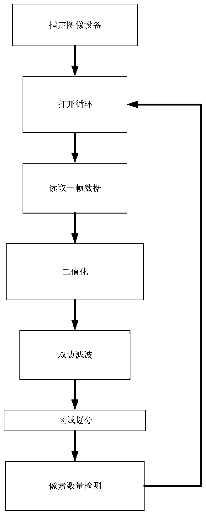
[0022] In order to solve the low precision and high price of traditional visual guides, the present invention proposes the following technical solutions: a design scheme for the application direction of machine vision technology in electronic blind guides:

[0023] Entity structure:

[0024] The device takes the blind guide stick as the main body, the Raspberry Pi development board is placed under the handle, and the camera is placed in front of the handle and placed at a certain angle obliquely downward.

[0025] According to the law of circular motion, the camera is located at the center of the hand, and the force is relatively small. After mastering the method of use, there will be no large displacement to make the detection subject out of the image collection range. Secondly, compared to placing it at the bottom of the blind stick, the camera can obtain a larger Field of view, while its image accuracy only depends on the resolution of the image sensor, and is not greatly a...


PUM


Abstract

The invention discloses an electronic blind guide instrument based on machine vision. The device takes a blind guide stick as a main body, a raspberry development board is arranged below a handle, anda camera is located in front of the handle and obliquely placed at a certain angle. According to a circular motion law, the camera is located in the circle center position of a handle and receives smaller force, deviation of a detection body from an image acquisition range due to larger displacement can be avoided after a use method is mastered, secondly, instead of being placed at the bottom ofthe blind guide stick, the camera can obtain a larger field of view, and meanwhile, the image accuracy of the camera only depends on the resolution of an image sensor and is slightly influenced by thedistance.

Description

technical field [0001] The invention belongs to the application field of machine vision technology, and relates to a design scheme of the application direction of machine vision technology in electronic blind guide equipment. Background technique [0002] Machine vision technology is a branch of artificial intelligence that is developing rapidly. Simply put, machine vision is the use of machines instead of human eyes for measurement and judgment. Through machine vision products (that is, image capture devices, which are divided into CMOS and CCD), the captured target is converted into an image signal, and sent to a dedicated image processing system to obtain the shape information of the captured target. According to the pixel distribution and brightness, color, etc. The information is transformed into digital signals; the image system performs various operations on these signals to extract the characteristics of the target, and then controls the on-site equipment actions ac...

Claims


Application Information

Patent Timeline
Patent Type & Authority Applications(China)
IPC IPC(8): A61H3/06G06F30/20G06K9/00G06N3/08
CPCA61H3/068A61H3/061G06F30/20G06N3/08G06V20/10
Inventor 陈鹏丁纪峰许爽龚思禄陆俊安
Owner DALIAN NATIONALITIES UNIVERSITY
Why Eureka
Try Eureka