Oscillator for clinical laboratory
An oscillator and laboratory technology, applied in the field of medical machinery, can solve the problems of fracturing the test tube wall, reducing the test dose, hidden dangers, etc., to achieve the effect of improving protection, increasing the accurate value of data volume, and fully oscillating inspection
- Summary
- Abstract
- Description
- Claims
- Application Information
AI Technical Summary
Problems solved by technology
Method used
Image
Examples
Embodiment 1
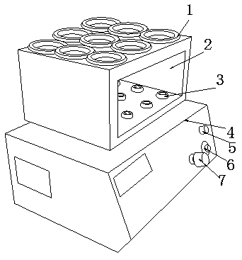
[0031] see Figure 1-Figure 6, the present invention provides a laboratory oscillator, its structure includes: test tube shaft collar 1, square frame groove 2, ball rubber concave cap push seat 3, integrated circuit seat 4, indicator light cover 5, contact switch seat 6, Rotating speed adjustment button 7, said ball rubber concave cap push seat 3 is installed in the inside of square frame groove 2 and is on the same bottom horizontal plane, said test tube shaft collar 1 is nested on the top of square frame groove 2 and penetrates each other, The square frame groove 2 is closely attached to the top surface of the integrated circuit holder 4, and the integrated circuit holder 4 is electrically connected with the indicator light cover 5, and the contact switch holder 6 is closely attached to the right side of the integrated circuit holder 4 and is in the On the same bottom slope, the rotational speed adjustment button 7 is mechanically connected to the integrated circuit seat 4, ...
Embodiment 2
[0037] see Figure 1-Figure 6 , the present invention provides a laboratory oscillator, other aspects are the same as embodiment 1, the difference is:
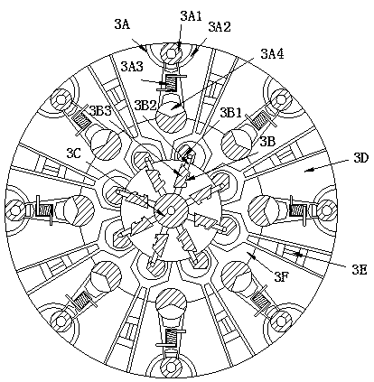
[0038] see figure 2 , the counterweight paddle frame 3B is composed of a paddle plate wheel groove 3B1, a short strut 3B2, and a counterweight slide block 3B3, and the paddle plate wheel groove 3B1 is nested on the top of the short strut 3B2, so The short strut 3B2 is mechanically connected with the counterweight sliding block 3B3 and is on the same oblique line, and the short strut 3B2 is driven to rotate through the paddle wheel groove 3B1 to turn the short strut 3B2 to form the relaxation and oscillation operation effect of the overall center bracket.
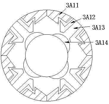
[0039] see Figure 5 The paddle plate wheel groove 3B1 is composed of a wheel groove body 3B11, a paddle blade plate 3B12, an ear plate seat 3B13, and a lock pin rod frame 3B14, and the paddle plate 3B12 is mechanically connected with the ear plate seat 3B13 and is in the...
PUM
 Abstract
Description
Claims
Application Information
 - R&D
- Intellectual Property
- Life Sciences
- Materials
- Tech Scout
- Unparalleled Data Quality
- Higher Quality Content
- 60% Fewer Hallucinations
Browse by: Latest US Patents, China's latest patents, Technical Efficacy Thesaurus, Application Domain, Technology Topic, Popular Technical Reports.
© 2025 PatSnap. All rights reserved.Legal|Privacy policy|Modern Slavery Act Transparency Statement|Sitemap|About US| Contact US: help@patsnap.com


