Non-woven carpet production line
A production line and carpet technology, applied in textiles and papermaking, spray/jet textile material treatment, coating, etc., can solve problems affecting the use of fabrics, achieve fast cooling, increase the contact area, and facilitate use
- Summary
- Abstract
- Description
- Claims
- Application Information
AI Technical Summary
Problems solved by technology
Method used
Image

Examples
Embodiment Construction
[0045] The present invention will be described in further detail below in conjunction with the accompanying drawings.
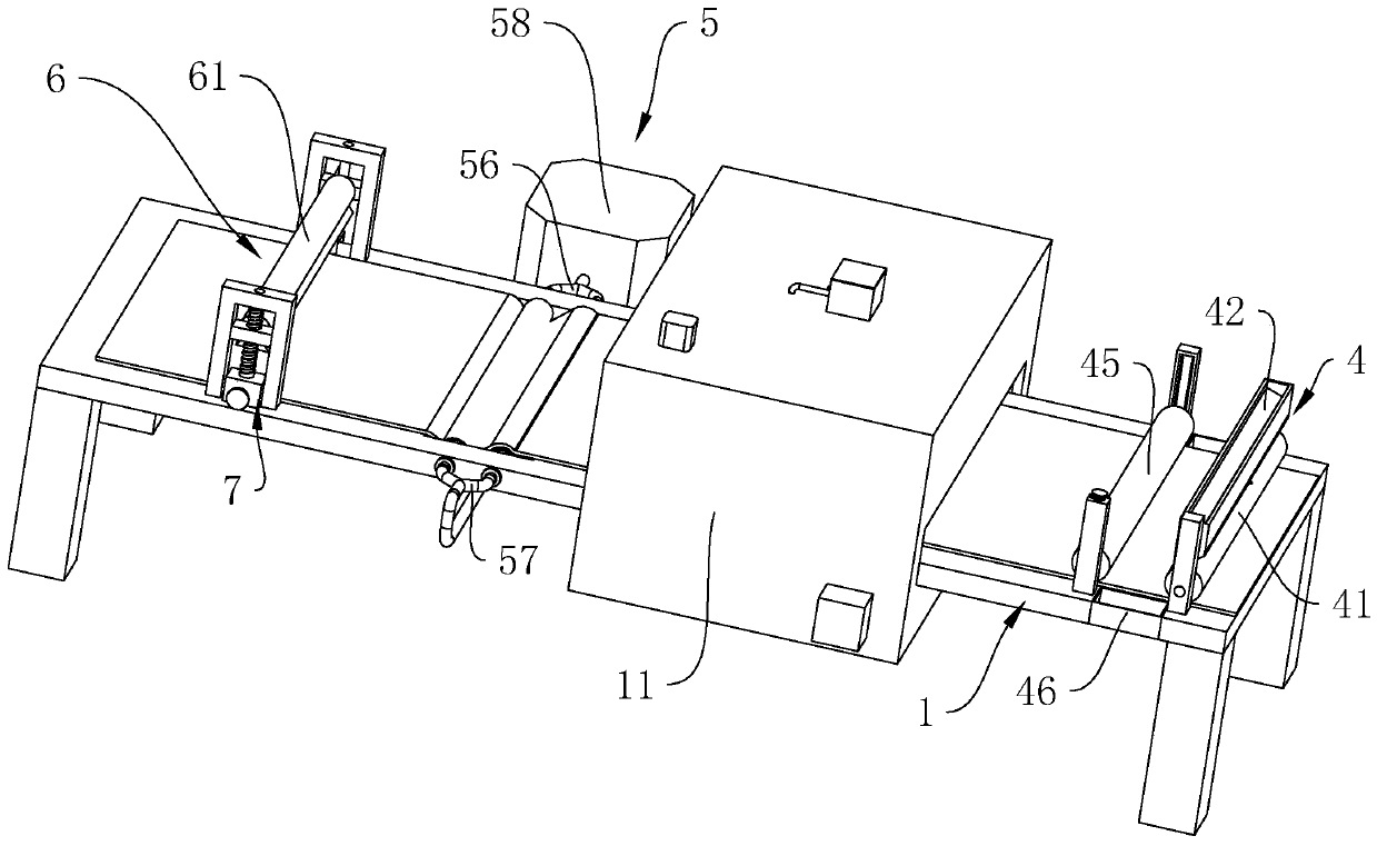
[0046] refer to figure 1 , figure 2 , is a non-woven carpet production line disclosed by the present invention, including a workbench 1 for installing production equipment, a drying box 11 for drying cloth is arranged on the workbench 1, and a pair of Drying unit for fabric drying. The drying component is a hot air pipe, and the hot air is sent to the hot air pipe by the hot air blower to dry the cloth. One side of the drying component is provided with a leveling component 2 .
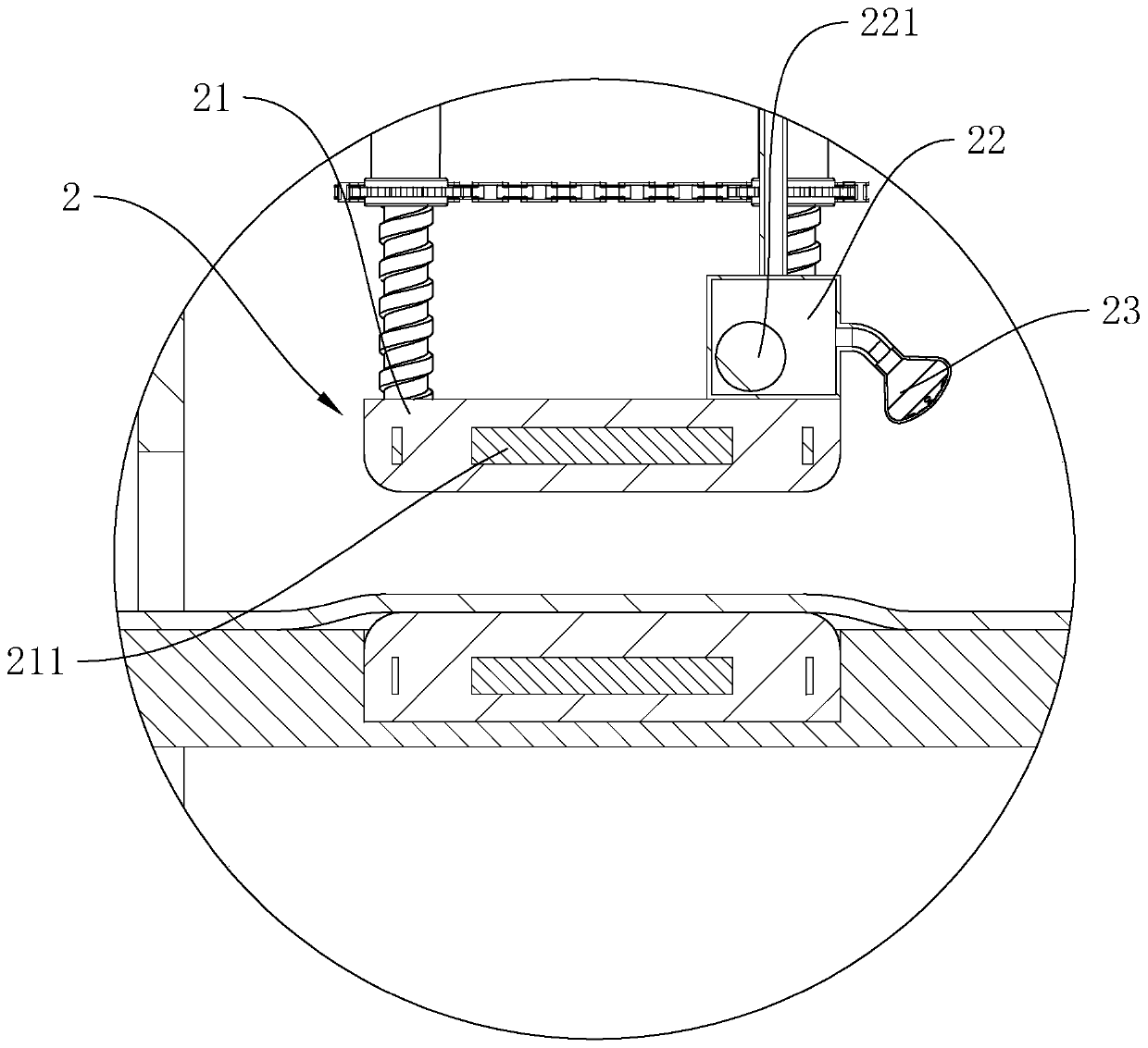
[0047] The leveling assembly 2 includes a pair of screeds 21 corresponding up and down. The shape of the two screeds 21 is preferably a square block with an arc-shaped side wall, and the material thereof is preferably metal. The screed 21 is also provided with an electric heating block 211 for heating the screed 21. The shape of the electric heating block 211 is preferably square...
PUM
 Abstract
Description
Claims
Application Information
PatSnap Eureka turns technology decisions into work you can execute. Powered by our Innovation Knowledge Graph, it runs expert workflows across engineering, life sciences, materials and intellectual property. Get your review-ready output in minutes.


