
Chip screening equipment

A technology for screening equipment and chips, which is applied in sorting and other directions, can solve problems such as collisions, low efficiency, and increased number of chips, and achieve the effect of reducing damage rate and high efficiency

Active Publication Date: 2020-08-25
江苏爱矽半导体科技有限公司
View PDF20 Cites 2 Cited by
  • Summary
  • Abstract
  • Description
  • Claims
  • Application Information

AI Technical Summary

Problems solved by technology

[0003] The purpose of the present invention is to provide a chip screening device. The method used to solve the chip screening is to use power to detect chips, and then use the manipulator to collect the detected chips in different containers according to the detection results. With the 5G chip Large-scale trial production, the number of chips carried on the same chip test board has greatly increased. At present, the chip test boards divided according to different grades only use a single manipulator to grip the method, which is inefficient. If multiple chips are used on the same chip test board The technical problem that the robot is easy to collide when picking up parts

Method used


Image

  • Chip screening equipment
  • Chip screening equipment
  • Chip screening equipment

Examples


Embodiment 1

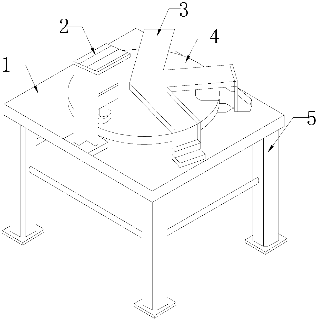
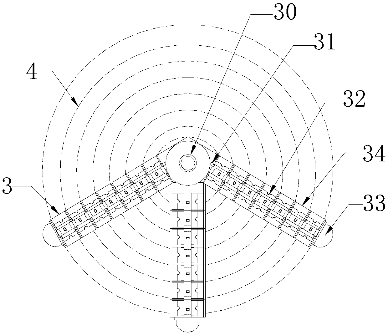
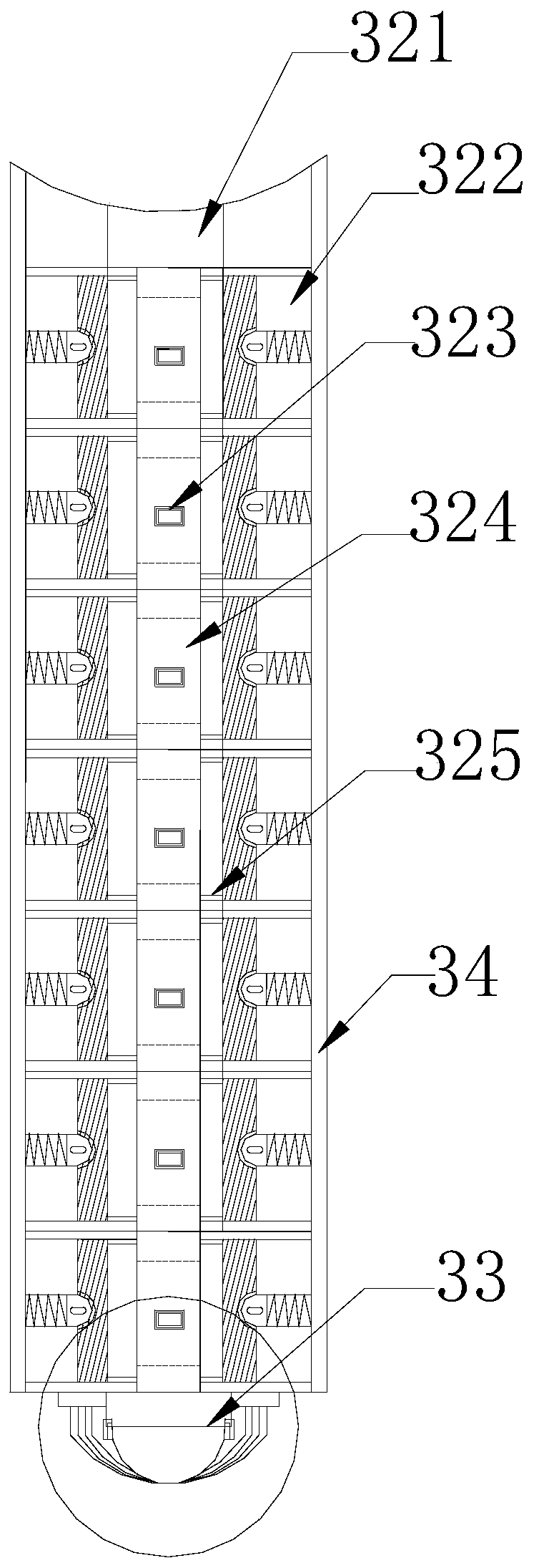
[0038] Such as Figure 1-Figure 7 As shown, the present invention provides a kind of chip screening equipment, and its structure comprises workbench 1, detection platform 2, sorting mechanism 3, test plate 4, support foot 5, and the bottom of described workbench 1 is equipped with four support feet 5, so The upper end of the workbench 1 is provided with a detection platform 2 and a test board 4. The test board 4 cooperates with the detection platform 2 and the sorting mechanism 3. The sorting mechanism 3 is a three-legged type, which can perform different levels of screening , the sorting mechanism 3 is composed of a rotating shaft 30, a push plate 31, a sorting guide 32, a transmission joint 33, and a rack 34, and the rotating shaft 30 is connected with three racks 34, and the rack 34 is horizontal More than two sorting guides 32 are installed in a straight line, and the transmission joint 33 is mechanically connected to the other end of the plate frame 34 relative to the rot...

Embodiment 2

[0048] Such as Figure 8-Figure 9 As shown, on the basis of Embodiment 1, through the mutual cooperation of the following component structures, the associated part 245 includes an outer cover 45a, an exhaust pipe 45b, a corrugated shaft 45c, a second spring 45d, and a top block 45e. The outer cover 45a Wrapped on the surface of the exhaust pipe 45b, the exhaust pipe 45b communicates with the inside of the corrugated shaft 45c, the inside of the corrugated shaft 45c is a standard atmospheric pressure, and the two ends of the second spring 45d are connected to the two ends of the corrugated shaft 45c Together, the second spring 45d is parallel to the corrugated shaft 45c, and the other end of the corrugated shaft 45c opposite to the exhaust pipe 45b is provided with a top block 45e, and the top block 45e has a semicircular structure.

[0049] The two sides of the middle suction cup 323 are equipped with connecting hinge wheels 23a and waist piece 23b, the waist piece 23b is arra...


PUM


Abstract

The invention discloses chip screening equipment. The chip screening equipment is characterized by structurally comprising a workbench, a detecting table, a sorting mechanism, a test board and supporting legs, wherein the bottom of the workbench is equipped with four supporting legs; the upper end of the workbench is provided with the detecting table and the test board; the test board is matched with the detecting table and the sorting mechanism; the sorting mechanism is of a three-foot type, and consists of a rotary shaft, a pushing plate, sorting guide parts, a transfer joint and plate racks, the rotary shaft is connected to the three plate racks, the plate racks are horizontally and linearly equipped with two or more sorting guide parts, and the transfer joint is mechanically connectedto the other ends, opposite to the rotary shaft, of the plate racks. The sorting mechanism is provided with the three plate racks, so that distinguishing can be achieved according to different screening grades, and therefore, efficiency is higher; the pushing plate, the sorting guide parts and the transfer joint, which are arranged on each plate rack, are mutually matched, the transfer joint is connected to a transfer belt, the pushing plate is matched on the plate racks, and workpieces screened out by the sorting guide parts are timely fed out to process, so that existing mechanical hand clamping type is changed, graded sorting and batch feeding are realized, and efficiency is high.

Description

technical field [0001] The invention relates to the technical field of semiconductor processing equipment, in particular to a chip screening equipment. Background technique [0002] Chip is an abbreviation of integrated circuit. Chip refers to a small semiconductor chip inside the integrated circuit package, that is, there are many varieties of die chips, and with the development of science and technology, it continues to increase. Thousands of pieces, up to tens of thousands of pieces, in order to ensure the dimensional accuracy of the chip, a piece of chip needs to be fully inspected by testing equipment, and according to different dimensional tolerances, the product is divided into three grades: excellent, good, and poor. Currently, for chip screening The method adopted is to use electricity to detect the chip, and then use the manipulator to collect the tested chips in different containers according to the test results. With the large-scale trial production of 5G chips, ...

Claims


Application Information

Patent Timeline
Patent Type & Authority Applications(China)
IPC IPC(8): B07C5/04B07C5/02B07C5/36
CPCB07C5/02B07C5/04B07C5/362
Inventor 李秀碧
Owner 江苏爱矽半导体科技有限公司
Learn More