Pipe conveying equipment not prone to falling

A technology for conveying equipment and pipes, applied in the field of pipe conveying equipment, can solve the problems affecting the safety and reliability of conveying, pipe misalignment or offset, damage to the chain plate motor, etc. the risk of falling, the effect of reducing adverse effects

Active Publication Date: 2020-08-25
DALIAN JIAOTONG UNIVERSITY
View PDF6 Cites 0 Cited by
  • Summary
  • Abstract
  • Description
  • Claims
  • Application Information

AI Technical Summary

Problems solved by technology

For the production of most pipe fittings, the inspection is generally carried out by random inspection, and the equipment for random inspection is generally located on the side of the conveying equipment. The final pipe fittings are placed on the conveying equipment to continue conveying. However, since the conveying equipment generally adopts chain plate or belt conveying equipment, however, for the current chain plate or belt conveying equipment, the conveying surface is generally smooth transition, generally It is a horizontal or inclined setting. In this way, when the sampling inspection manipulator grabs and places the pipe fittings, because the pipe fittings are generally heavy, and because of the rigidity, when picking and placing, especially when placing the pipe fittings, The chain plate is easily subject to great vibration, which not only easily damages the chain plate motor, but also easily causes the pipe to be misaligned or shifted, resulting in the pipe being scattered
[0003] Moreover, for equipment that is conveyed obliquely, due to the random inspection during transportation, when the pipes that have passed the inspection are placed on the conveying equipment, pipe fittings are often placed at various positions on the conveying equipment, causing the pipes to be very damaged. It is difficult to accurately place on the chain plate, even if it is placed, there will be a risk of the pipe fittings being scattered during the transportation process, which will affect the safety and reliability of the transportation

Method used


Image

  • Pipe conveying equipment not prone to falling
  • Pipe conveying equipment not prone to falling
  • Pipe conveying equipment not prone to falling

Examples


Embodiment Construction

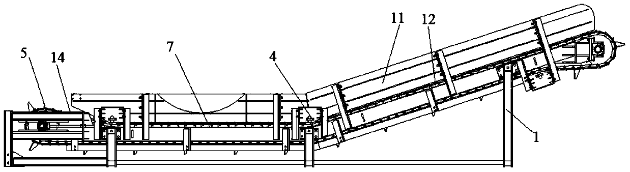
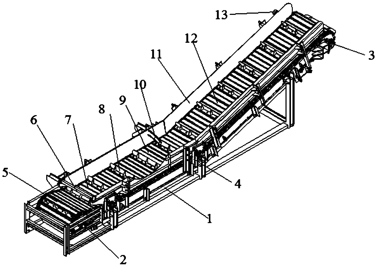
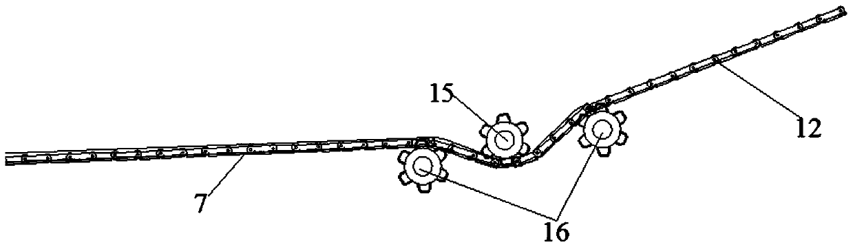
[0023] see Figures 1 to 5 , in an embodiment of the present invention, a pipe conveying equipment that is not easy to fall includes a frame 1, a driven sprocket 2, a driving sprocket 3, a conveying chain plate assembly 7 and a limit baffle 11, wherein the One side of the frame is provided with the driven sprocket, the other side of the frame is provided with the driving sprocket, and the driving sprocket is located obliquely above the driven sprocket, and the driven sprocket is arranged on the other side of the frame. Between the movable sprocket 2 and the driving sprocket 3, the conveying chain plate assembly is wound, and the two sides of the conveying chain plate assembly are provided with the limit baffles fixed on the frame, which is characterized in that It includes at least one set of auxiliary sprocket assemblies and at least one set of material receiving buffer mechanism 10, wherein each set of auxiliary sprocket assemblies is arranged at a position where pipes are p...


PUM


Abstract

The invention discloses pipe conveying equipment not prone to falling. The pipe conveying equipment not prone to falling can well achieve conveying of pipes, and facilitates putting down of the pipesafter spot check of a detection mechanical arm. When the mechanical arm puts down the pipes, the adverse effect of the pipes on the conveying equipment is effectively reduced, the oscillation phenomenon is reduced, the pipe conveying reliability is effectively guaranteed, the risk of falling of the pipes is reduced, the pipe conveying stability and reliability are effectively guaranteed, and the pipe conveying safety is improved. Meanwhile, the pipes can be conveniently taken and put through a pumping check taking and putting mechanical arm, the pipe taking and putting space is guaranteed, seamless joint of the pumping check taking and putting mechanical arm and the pipe conveying equipment is achieved, and the pipe conveying safety is improved.

Description

technical field [0001] The invention specifically relates to a pipe conveying equipment that is not easy to drop, and belongs to the field of pipe conveying equipment. Background technique [0002] For the batch processing and production of pipes, the flow-through method is generally used to realize processing, production and testing. After the pipe is produced, it needs to be transported to the processing and testing station by conveying equipment for subsequent processing and testing. For the production of most pipe fittings, the inspection is generally carried out by random inspection, and the equipment for random inspection is generally located on the side of the conveying equipment. The final pipe fittings are placed on the conveying equipment to continue conveying. However, since the conveying equipment generally adopts chain plate or belt conveying equipment, however, for the current chain plate or belt conveying equipment, the conveying surface is generally smooth t...

Claims


Application Information

Patent Timeline
Patent Type & Authority Applications(China)
IPC IPC(8): B65G17/46B65G17/06
CPCB65G17/061B65G17/46B65G2201/0276
Inventor 沙智华王国庆宋秀莹
Owner DALIAN JIAOTONG UNIVERSITY
Why Eureka
Try Eureka