
Manufacturing process of self-propelled movable formwork main beam structure and main beam structure

A technology of mobile formwork and manufacturing process, which is applied in the direction of erecting/assembling bridges, bridges, bridge construction, etc. It can solve the problems of unsuitable overall straightness, large cross-sectional size of components, and difficulty in the process, so as to ensure that the holes are concentric High degree and verticality, good flatness, improve the effect of production accuracy

Active Publication Date: 2020-08-25
广州文冲船舶修造有限公司
View PDF6 Cites 0 Cited by
  • Summary
  • Abstract
  • Description
  • Claims
  • Application Information

AI Technical Summary

Problems solved by technology

[0005] The manufacturing precision of the steel components of the mobile formwork is high, the cross-sectional size of the components is large, and the weight of a single piece is heavy, making it difficult to manufacture, assemble, turn over, weld and other processes. The joints between the sections, between the sections of the guide beam and between the main beam and the guide beam are prone to deformation during the assembly and welding process, resulting in the overall straightness not meeting the requirements. Therefore, the main beam and guide beam manufacturing process How to control deformation and improve assembly accuracy is an important issue

Method used


Image

  • Manufacturing process of self-propelled movable formwork main beam structure and main beam structure
  • Manufacturing process of self-propelled movable formwork main beam structure and main beam structure
  • Manufacturing process of self-propelled movable formwork main beam structure and main beam structure

Examples


Embodiment 1

[0034]In describing the present invention, it should be understood that the terms "center", "longitudinal", "transverse", "upper", "lower", "front", "rear", "left", "right", " The orientations or positional relationships indicated by "vertical", "horizontal", "top", "bottom", "inner" and "outer" are based on the orientations or positional relationships shown in the drawings, and are only for the convenience of describing the present invention and Simplified descriptions, rather than indicating or implying that the device or element referred to must have a particular orientation, be constructed and operate in a particular orientation, and thus should not be construed as limiting the invention.

[0035] Embodiment 1 of the present invention provides a manufacturing process for the main girder of the self-propelled mobile formwork. The manufacturing process of the main beam of the mobile formwork is limited to this type of mobile formwork.

[0036] The main beam structure of thi...

Embodiment 2

[0069] An embodiment of the present invention provides a main beam structure of a self-propelled mobile formwork, which is manufactured using the above manufacturing process. The main girder structure of the self-propelled mobile formwork has good overall straightness, small deformation, high manufacturing precision and good quality.


PUM

PropertyMeasurementUnit
Thicknessaaaaaaaaaa

Abstract

The invention relates to a manufacturing process of a self-propelled movable formwork main beam structure. The process comprises the following specific operation steps: 1) manufacturing a main beam body; 2) manufacturing a guide beam; 3) manufacturing a bottom die truss; and 4) assembling the main beam structure. According to the manufacturing process of the self-propelled movable formwork main beam structure, manufacturing precision is controlled through a reversible deformation jig frame and a reasonable technological process, and the manufactured main beam structure is good in overall straightness, high in precision, convenient to transport and assemble, high in construction and manufacturing speed, beneficial to shortening a construction period and capable of saving construction cost.

Description

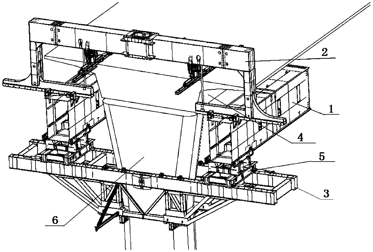
technical field [0001] The invention relates to the technical field of self-propelled mobile formwork, in particular to a manufacturing process and main beam structure of a self-propelled mobile formwork main beam structure. Background technique [0002] Mobile formwork, also known as sliding formwork support system and MSS bridge building machine, is a construction machine with its own formwork, which uses caps or pier columns as supports to cast bridges on site. As an advanced construction equipment, due to the advantages of good construction quality, easy operation and high efficiency, mobile formwork has been widely used in the continuous beam construction of highways, road bridges and railway bridges. [0003] Mobile formwork is divided into two types: self-propelled mobile formwork and non-self-propelled mobile formwork. Self-propelled mobile formwork is widely used because of its own function. Please refer to figure 1 , figure 1 It is a structural schematic diagram...

Claims


Application Information

Patent Timeline
IPC IPC(8): E01D21/00E01D2/04
CPCE01D2/04E01D21/00
Inventor 钟伟怀古新年肖文伟
Owner 广州文冲船舶修造有限公司
Learn More