Experiment table using magnetic field force to change volume weight of cement sand and gravel dam model test piece
A technology of cemented sand and gravel dams and test benches, which is applied in hydraulic models, hydraulic engineering, sea area engineering, etc., can solve the problems of the development speed of related disciplines that affect the progress of experiments, increase the consumption of experimental materials, and do not meet the actual force conditions, etc. problem, to achieve the effect of simple structure, convenient operation and reduced error
- Summary
- Abstract
- Description
- Claims
- Application Information
AI Technical Summary
Problems solved by technology
Method used
Image
Examples
Embodiment 1
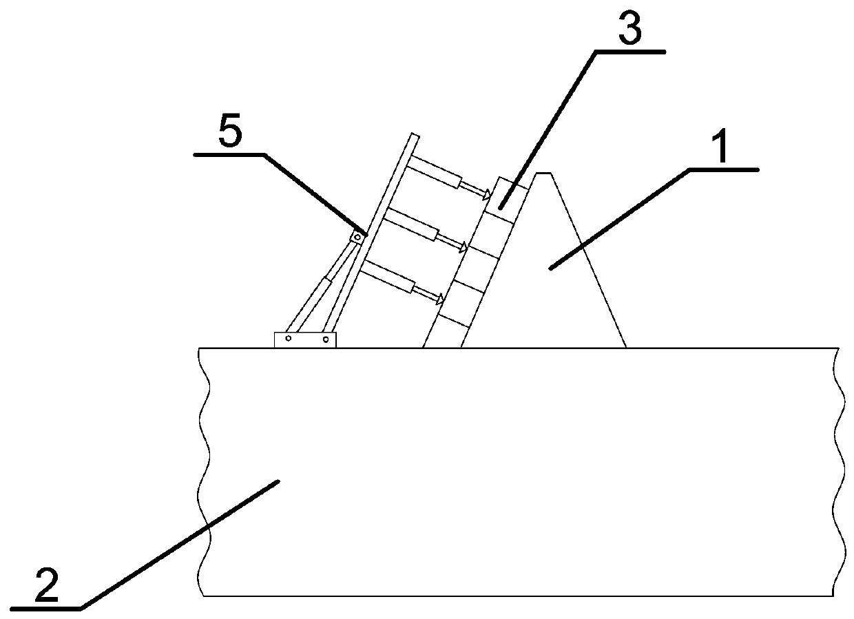
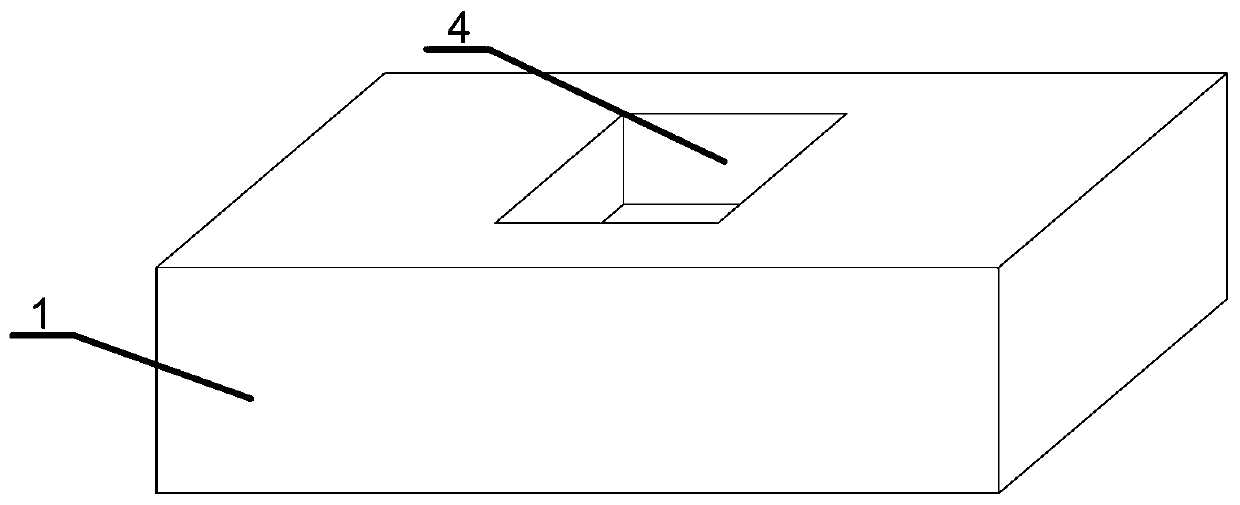
[0041] This embodiment provides a kind of experimental bench that utilizes magnetic force to change the bulk density of cemented sand and gravel dam model specimens, such as figure 1 and figure 2 Shown includes a dam body model specimen 1 and a test bench 2 with a rectangular parallelepiped structure. The aggregate component of the dam body model specimen 1 is iron powder. The material is a diamagnetic substance.
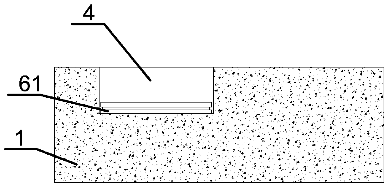
[0042] Such as Figure 3-6 As shown, the magnetic field groove is provided with a magnetic field unit, the magnetic field unit includes a base 61, a film support plate 62 and a permanent magnet 63, the base 61 is a gypsum material base, the base 61 is bonded to the middle of the bottom of the magnetic field groove 4, and the top of the base 61 There is a magnet installation groove 611 downwards in the middle of the end face, and the permanent magnet 63 is matched and inserted into the magnet installation groove 611 of the base 61. Since the material of the base 6...
Embodiment 2
[0067] The difference between embodiment 2 and embodiment 1 lies in the way of fixing the film support plate.
[0068] Such as Figure 7 As shown, the test bench 2 at the notch of the magnetic field groove 4 is fixed with a fixed limit frame 64, and the diameter of the inner frame mouth of the fixed limit frame 64 is greater than the size of the notch of the magnetic field groove 4, and the magnetic field groove 4 is located at the fixed limit. In the position frame 64, the film support plate 62 is matched and installed in the fixed limit frame 64. Since the diameter of the inner frame opening of the fixed limit frame 64 is greater than the size of the magnetic field groove 4 notches, the film support plate 62 is directly blocked. On the magnetic slot 4.
[0069] Compared with Embodiment 1, the film support plate 62 on the test bench of this embodiment is matched and installed in the fixed limit frame 64, and it is not necessary to use glue to fix the film support plate 62. W...
Embodiment 3
[0071] The difference between embodiment 3 and embodiment 2 lies in the way of fixing the film support plate.
[0072] Such as Figure 8 As shown, the test bench 2 of this embodiment is formed by direct pouring of concrete, which is characterized by high strength and low manufacturing cost. The middle part of the upper end surface of the test bench 2 is provided with a magnetic field groove 4 downwards, such as Figure 9 As shown, the upper mouth of the magnetic field groove 4 is provided with a ring frame groove 65 outwards along the groove wall, and the magnetic field groove 4 and the ring frame groove 65 are all reserved grooves preset when pouring the test bench 2, which is the same as that of the embodiment. 2. Compared with the slotting method of the magnetic field slot 4, the device of this embodiment reduces the slotting time of the magnetic field slot 4 and saves time and cost.
[0073]When in use, the film support plate 62 is directly matched and blocked and install...
PUM
 Abstract
Description
Claims
Application Information
 - R&D
- Intellectual Property
- Life Sciences
- Materials
- Tech Scout
- Unparalleled Data Quality
- Higher Quality Content
- 60% Fewer Hallucinations
Browse by: Latest US Patents, China's latest patents, Technical Efficacy Thesaurus, Application Domain, Technology Topic, Popular Technical Reports.
© 2025 PatSnap. All rights reserved.Legal|Privacy policy|Modern Slavery Act Transparency Statement|Sitemap|About US| Contact US: help@patsnap.com


