Data-driven accurate regulation and control method for urban central heating system

A centralized heating and data-driven technology, applied in heating systems, heating methods, household heating, etc., can solve problems such as high control costs, low utilization efficiency, and energy waste

Active Publication Date: 2020-08-25
ZHEJIANG UNIV
View PDF5 Cites 15 Cited by
  • Summary
  • Abstract
  • Description
  • Claims
  • Application Information

AI Technical Summary

Problems solved by technology

[0002] The heating system produces high-temperature hot water in the heat source plant and drives the hot water to circulate in the primary side pipe network to deliver heat energy to each thermal station. In the thermal station, the primary side and the secondary side perform heat exchange to transfer heat from the primary side to the secondary side. The heat is exchanged from the secondary side to the secondary side, and the secondary side supplies heat to each

Method used


Image

  • Data-driven accurate regulation and control method for urban central heating system
  • Data-driven accurate regulation and control method for urban central heating system
  • Data-driven accurate regulation and control method for urban central heating system

Examples


Embodiment 1

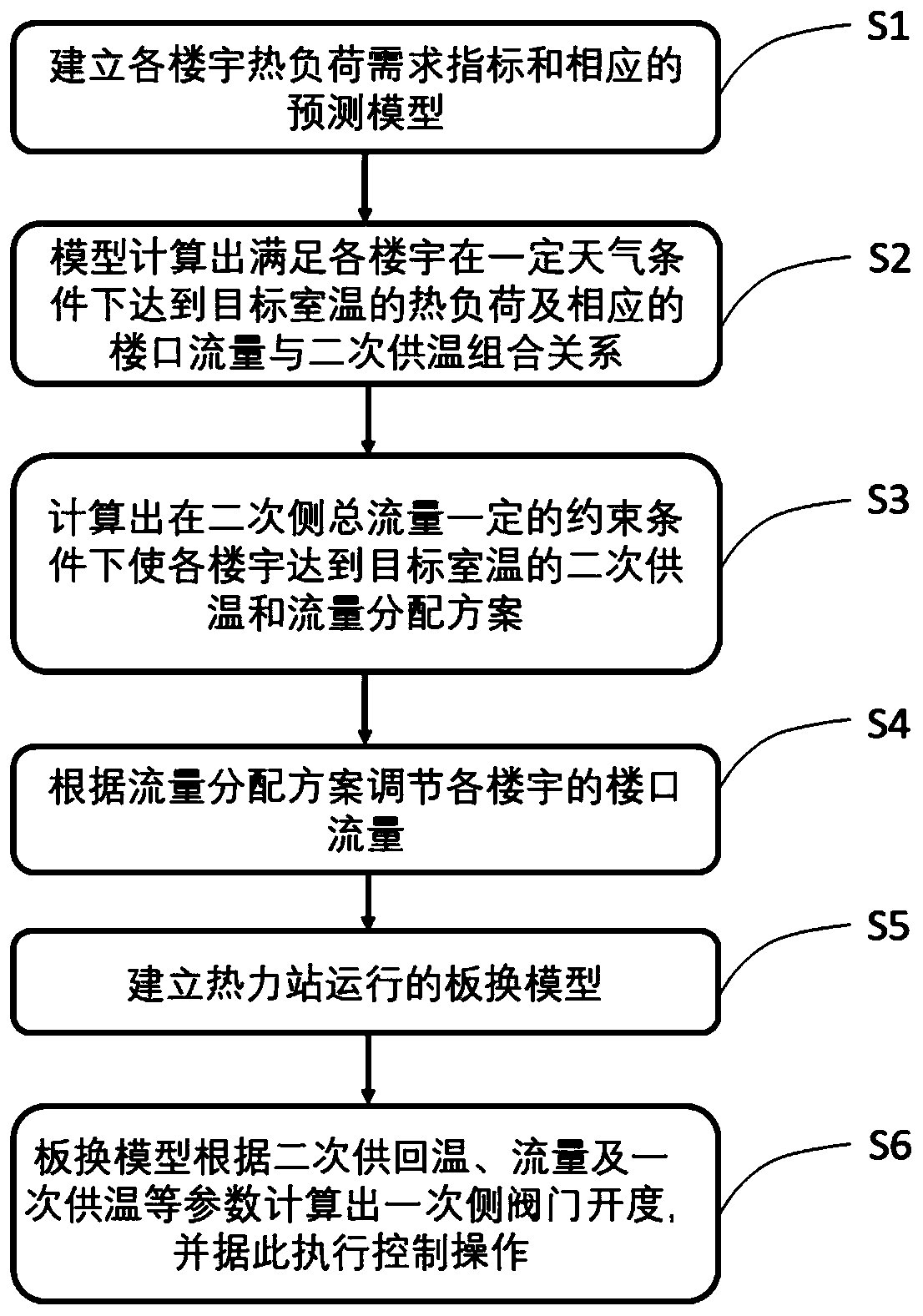
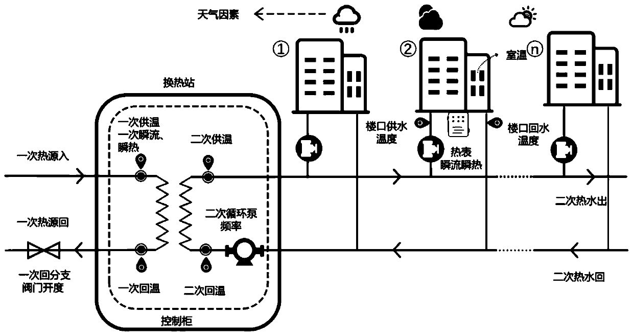
[0099] combine figure 1 , figure 2 and image 3 , the present invention relates to a data-driven precise control method for urban central heating systems, specifically comprising the following steps:

[0100] Step S1, establishing heat load demand indexes and corresponding prediction models for each building;

[0101] Step S2, using the predictive model to calculate the heat load that meets the target room temperature of each building under certain weather conditions and the corresponding combination relationship between the building flow and the secondary side heating;

[0102] Step S3, calculating the secondary side supply and flow distribution scheme for each building to reach the target room temperature under certain constraint conditions of the secondary side total flow;

[0103] Step S4, adjusting the entrance flow of each building according to the flow distribution plan;

[0104] Step S5, establishing a plate replacement model for the operation of the thermal stati...

Embodiment 2

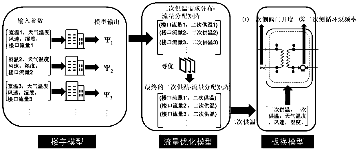
[0141] On the basis of Example 1, combined with image 3 , this embodiment 2 provides a central heating system on-demand precise control system, including:

[0142] A model building module, used for building a building heat load demand forecasting model;

[0143] The optimization module of flow at the floor opening and the temperature supply at the secondary side, that is, image 3 The flow optimization model in is used to calculate the secondary side supply and the corresponding floor flow distribution scheme to make the building reach the target room temperature;

[0144] The thermal station primary side valve operation adjustment model building module is used to obtain the thermal station plate exchange rate obtained through training according to the current primary side temperature supply, secondary side return temperature, secondary side flow rate, and the secondary side temperature supply to be achieved. The model calculates the opening degree of the primary side valve...


PUM


Abstract

The invention relates to a data-driven accurate regulation and control method for an urban central heating system. The method comprises the following steps of Step 1, establishing a heat load demand index of each building and a corresponding prediction model; Step 2, according to the prediction model, calculating a heat load of each building reaching a target room temperature under a certain weather condition and the corresponding relationship of the building entrance flow and secondary temperature supply combination; Step 3, calculating a secondary temperature supply and flow distribution scheme enabling each building to reach the target room temperature under the constraint condition that the total flow of the secondary side is certain; Step 4, adjusting the building entrance flow of each building according to the flow distribution scheme; Step 5, establishing a plate exchange model for the operation of a heating station; and Step 6, calculating the opening degree of a primary side valve through the plate exchange model, and executing the control operation according to the opening degree of the primary side valve. The method provided by the invention has the advantages that a common electric control valve is arranged at the entrance of the building of the secondary side, the opening degree of the valve is calculated by a control system, and an electric signal is sent to the electric control valve, so that the control cost at each building is reduced.

Description

technical field [0001] The invention belongs to the field of advanced control of heating systems, and in particular relates to a method and system for model-predicting the load of each building on the secondary side and optimizing the flow of each building in order to realize on-demand precise regulation of the central heating system . Background technique [0002] The heating system produces high-temperature hot water in the heat source plant and drives the hot water to circulate in the primary side pipe network to deliver heat energy to each thermal station. In the thermal station, the primary side and the secondary side perform heat exchange to transfer heat from the primary side to the secondary side. The heat is exchanged from the secondary side to the secondary side, and the secondary side supplies heat to each heat user in the secondary side pipe network. However, the current thermal power station cannot accurately predict the specific load demand of each heat user. ...

Claims


Application Information

Patent Timeline
IPC IPC(8): F24D19/10G06F30/13G06F119/08
CPCF24D19/1015G06F30/13G06F2119/08
Inventor 钟崴封恩程林小杰黄伟王丽腾
Owner ZHEJIANG UNIV
Why Eureka
Try Eureka