Heat dissipation structure for motor

A technology of heat dissipation structure and heat dissipation holes, which is applied to electrical components, electromechanical devices, electric components, etc., can solve problems such as poor heat dissipation effect, damage to the motor, and vibration, and achieve the effect of small vibration of the device

Inactive Publication Date: 2020-08-25
嘉兴欧洛扬机械有限公司
View PDF7 Cites 1 Cited by
  • Summary
  • Abstract
  • Description
  • Claims
  • Application Information

AI Technical Summary

Problems solved by technology

[0003] When the motor is in use, a lot of heat will be generated, but the heat is removed through the cooling holes on the surface of the motor, the cooling effect is poor, and the motor must be stopped after working for a period of time, resulting in loss, and there is vibration during use, which will damage the motor motor

Method used


Image

  • Heat dissipation structure for motor
  • Heat dissipation structure for motor
  • Heat dissipation structure for motor

Examples


Embodiment Construction

[0026] The technical solutions in the embodiments of the present invention will be clearly and completely described below in conjunction with the accompanying drawings in the embodiments of the present invention. Obviously, the described embodiments are only a part of the embodiments of the present invention, rather than all the embodiments.

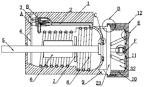
[0027] Reference Figure 1-8 , A heat dissipation structure for a motor, including a housing 1, an output shaft 5 is installed inside the housing 1, a first fan blade 7 is mounted on the outer surface of the output shaft 5, and the outer surface of the output shaft 5 and the first fan blade 7 The inner surface is welded to make the fixation firmer and more convenient.

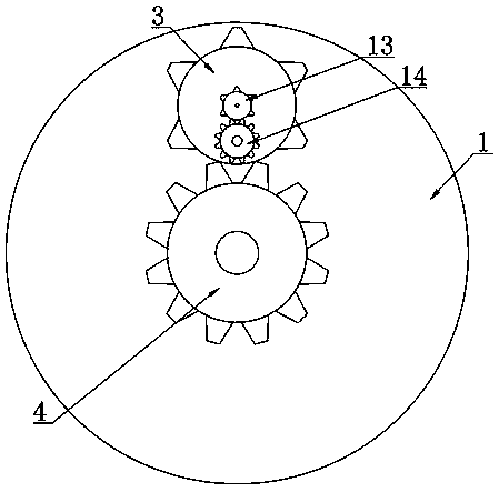
[0028] The housing 1 and the output shaft 5 are rotatably connected by bearings. The surface of the output shaft 5 is mounted with a drive block 6, and the output shaft 5 is fixedly connected with the drive block 6. A second gear 4 and an output shaft 5 are mounted on one side...


PUM


Abstract

The invention relates to the technical field of motors, and particularly relates to a heat dissipation structure for a motor. The heat dissipation structure comprises a shell, an output shaft is mounted in the shell, and the shell is rotationally connected with the output shaft through a bearing; a first fan blade can dissipate heat, thereby achieving an air cooling effects, water in a second pipeline achieves a water cooling effect, and dual layer cooling is formed; a second fan blade rotates to enable water to flow, the temperature of the water is quickly reduced, and effective heat exchangecan be realized; a conical fan blade rotates to enable water to generate vortexes, and the water flow rate is increased again; a second rubber layer extrudes, air in a fixed cylinder is extruded, resistance is generated, and shock is reduced; the elasticity of the second rubber layer, a first rubber layer and a third spring can absorb shock again and protect a movable block; a third clamping block moves to extrude the elastic rubber to absorb shock again on the device; the first spring absorbs shock on the device; and the shock of the device is minimized through multiple times of shock absorption.

Description

Technical field [0001] The invention relates to the technical field of motors, and in particular to a heat dissipation structure for motors. Background technique [0002] The main function of the motor is to generate driving torque, as the power source for electrical appliances or various machinery. The generator is represented by the letter G in the circuit. Its main function is to convert mechanical energy into electrical energy. [0003] When the motor is in use, a lot of heat is generated, but the heat is removed through the heat dissipation holes on the surface of the motor, and the heat dissipation effect is poor. The motor must be stopped after working for a period of time, resulting in loss, and vibration during use, which will cause damage Motor. Summary of the invention [0004] The purpose of the present invention is to solve the shortcomings in the prior art, and proposes a heat dissipation structure for a motor. One fan blade can effectively dissipate heat and play a r...

Claims


Application Information

Patent Timeline
Patent Type & Authority Applications(China)
IPC IPC(8): H02K9/06H02K9/19H02K5/20H02K5/24
CPCH02K5/20H02K5/24H02K9/06H02K9/19
Inventor 查春熙
Owner 嘉兴欧洛扬机械有限公司
Why Eureka
Try Eureka