Using method of machining and clamping device used for screen display diffraction supporting component

A technology of supporting parts and clamping devices, which is applied in the direction of positioning devices, metal processing equipment, metal processing machinery parts, etc., can solve the problem of the accuracy of the screen display diffraction support parts and connecting parts, the position size is out of tolerance, and the screen display diffraction support parts Incomplete stress release affects pilot observation, recognition, control and other issues, achieving the effect of easy manufacturing, reduced part deformation, and simple structure

Pending Publication Date: 2020-08-28
洛阳福东机械有限公司
View PDF0 Cites 0 Cited by
  • Summary
  • Abstract
  • Description
  • Claims
  • Application Information

AI Technical Summary

Problems solved by technology

[0003] The purpose of the present invention is to overcome the existing screen display diffractive support parts through machine tool processing, due to the complex structure, the material has stretch characteristics after being subjected to temperature changes, during processing, the stress release inside the screen display diffractive support parts is not complete, and the processing Deformation, the accuracy of the cooperation between the screen display diffraction support part and the connecting part, and the position and size are out of tolerance. When the screen display diffraction support part is deformed, it will affect the positioning accuracy of the screen display diffraction connection part. These problems are common in the industry It has been difficult to solve the complicated and miscellaneous diseases. The deformation of the screen display diffraction support parts affects the information received and transmitted by the connecting parts, and directly affects the pilot's observation, identification, and control; through a reasonable design, a processing of the screen display diffraction support parts is now provided. The use method of the clamping device; the screen display diffraction support part of the present invention can largely avoid the internal stress generated during the casting of the blank through the pre-heat treatment of the blank state, and avoid the post-process processing with internal stress. ;Release the processing stress of the blank to ensure the consistency of the part size

Method used


Image

  • Using method of machining and clamping device used for screen display diffraction supporting component
  • Using method of machining and clamping device used for screen display diffraction supporting component
  • Using method of machining and clamping device used for screen display diffraction supporting component

Examples


Embodiment 1

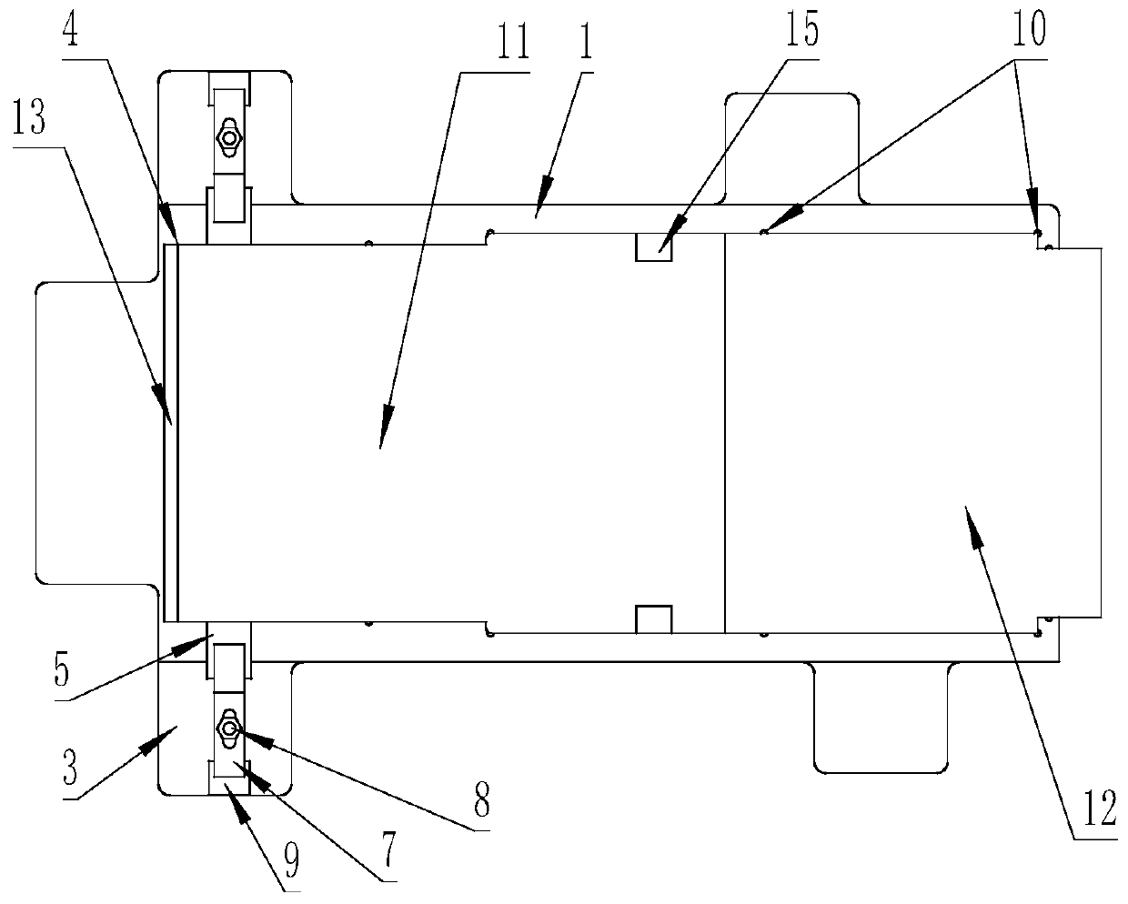
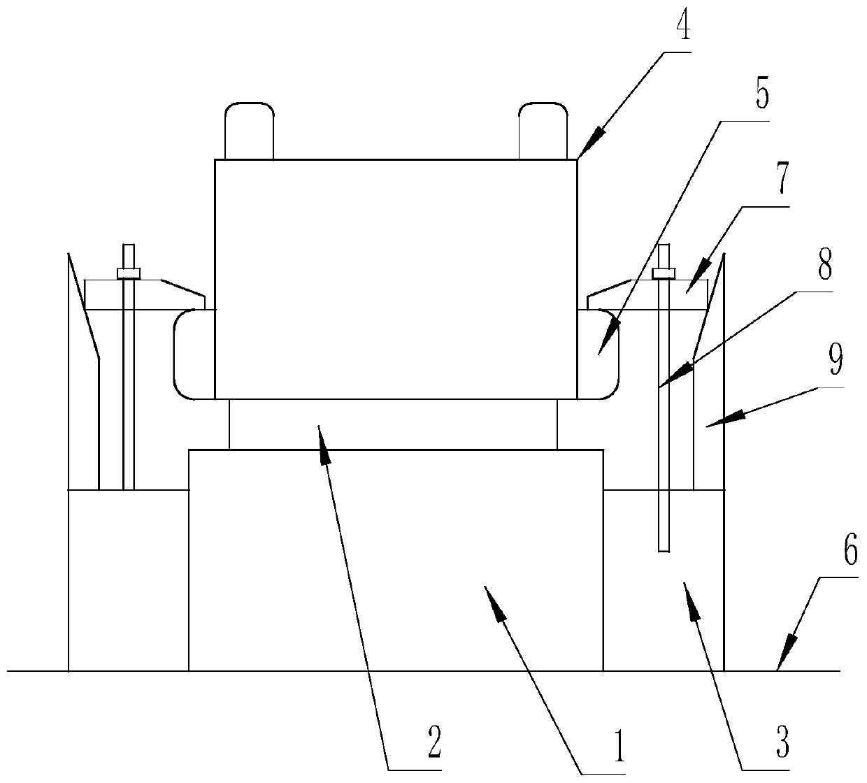
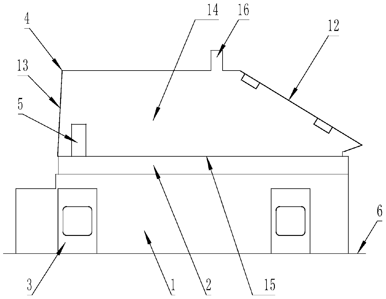
[0021] The clamping base 1 is set on the working table 6, and the padding block 2 is set on the clamping base 1, and the part blank 4 is set on the topping block 2; 11. The right end of the component blank 4 is set as a front inclined surface 12, and the left end of the component blank 4 is set as a rear slope surface 13; the two sides of the component blank 4 are set as a pair of side surfaces 14; Base T-shaped ears 3, a pair of component side hinged ear seats 5 are symmetrically arranged on both sides of the rear part below a pair of side surfaces 14, and a pair of component side hinged ear seats 5 and a pair of base T-shaped ears 3 are arranged correspondingly up and down; the bottom surface of the blank 11. A pair of bottom hinged ear seats 16 are arranged symmetrically on both sides above the right end;

[0022] A pair of T-shaped ears of the base 3 are symmetrically reserved in the middle for the position space for the installation of the pressure plate, and a screw hole...

Embodiment 2

[0025] After the component blank 4 has been treated with high and low temperature for two times, the pair of bottom hinged ear seats 16 of the component blank 4 are released, and the blank bottom surface 11 of the component blank 4 is placed on the raised block 2 in the center of the workbench 6 for positioning, and the component blank 4. After positioning, rotate the nuts on the bolts 8 on both sides to rotate and press down the pressure plate 7 to press and fix the component blank 4. After the component blank 4 is clamped and fixed, the blank base surface 15 of the component blank 4 is reserved by the machine tool. amount of milling;

[0026] After the blank base surface 15 is milled, the blank base surface 15 of the component blank 4 is turned downward, and the nuts on the bolts 8 are rotated through the pressure plate 7. The two ends are respectively passed through the standard heightening block 9 and the component side hinge ear seat 5. Clamping and fixing, the first mill...

Embodiment 3

[0028] After the rough machining is completed by machining the large margin on the outside of the component blank 4, the pressure plates 7 on both sides of the component blank 4 are removed, and the component blank 4 undergoes a second round of high and low temperature aging heat treatment. The blank 4 undergoes a second round of high and low temperature aging heat treatment, and the second round of high and low temperature aging heat treatment of the component blank 4 is: stabilization treatment of the component blank 4 .

[0029] After the stabilization treatment of the component blank 4 is completed, the repeated component blank 4 is placed on the height block 2 for positioning, clamping and fixing again, and the outer surface of the component blank 4 is processed by the machine tool for semi-finishing, and the surface of the component blank 4 after semi-finishing 1. Reserve a margin of 0.3mm to 0.5mm on one side of the hole.


PUM


Abstract

The invention discloses a using method of a machining and clamping device used for a screen display diffraction supporting component. A clamping base is arranged on a workbench, a heightening block isarranged on the clamping base, and a component blank is arranged on the heightening block; before the component blank is machined, two rounds of high-low temperature aging heat treatment are conducted on the component blank, and then milling and rough machining are sequentially conducted with large allowance; semi-finish machining and finish milling machining are conducted on the component blank,a pressing plate is detached after finish milling machining is completed, the screen display diffraction supporting component with the component blank obtained after finish machining as a finished product is taken down to be packaged, and machining of the screen display diffraction supporting component is completed; and according to the screen display diffraction supporting component, through preheating treatment on a blank state, internal stress can be avoided to a great extent, part deformation is reduced, mutual cooperation and relative positions of parts can be guaranteed, precision afterlong-term use can be guaranteed, the machining quality stability of the modified parts is improved, and it is ensured that a pilot can accurately observe, identify and control.

Description

technical field [0001] The invention relates to the use of a processing and clamping device for screen display diffractive parts, in particular to a method for using the processing and clamping device for screen display diffractive supporting parts. Background technique [0002] At present, modern head-up displays place the screen in front of the cockpit to display important information to the pilot in intuitive forms such as images and characters. The pilot controls the flight information and its equipment through the positioning data, and the pilot can grasp the information while looking ahead. Relevant and important information put the two together for observation and identification; when the screen display diffraction support part is processed by the machine tool, due to the complex structure, the material has stretch characteristics after being subjected to temperature changes. During processing, the internal stress of the screen display diffraction support part is relea...

Claims


Application Information

Patent Timeline
Patent Type & Authority Applications(China)
IPC IPC(8): B23C3/00B23Q3/08B23Q17/00C21D1/78C21D1/773C21D9/00
CPCB23C3/00B23Q3/08B23Q3/084B23Q17/00C21D1/773C21D1/78C21D9/0068
Inventor 董浩然武自垒姚正伟
Owner 洛阳福东机械有限公司
Why Eureka
Try Eureka