LED colored lamp for building decoration

A technology for lanterns and buildings, which is applied in sustainable buildings, lighting devices, components of lighting devices, etc., can solve the problems of complex lighting installation routes, large equipment footprint, and difficult construction, and achieve vivid lighting dynamic effects. , prolong the service life, the effect of low construction difficulty

Active Publication Date: 2020-08-28
宁波谦屹节能科技有限公司
View PDF9 Cites 1 Cited by
  • Summary
  • Abstract
  • Description
  • Claims
  • Application Information

AI Technical Summary

Problems solved by technology

However, most of the existing LED lights change the light flicker frequency through electronic programs. Since the electronic programs rely on computers and other equipment to control, the installation route of the lamps

Method used


Image

  • LED colored lamp for building decoration
  • LED colored lamp for building decoration
  • LED colored lamp for building decoration

Examples


Embodiment 1

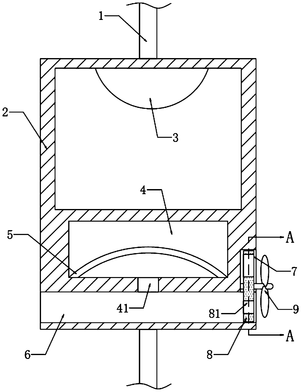
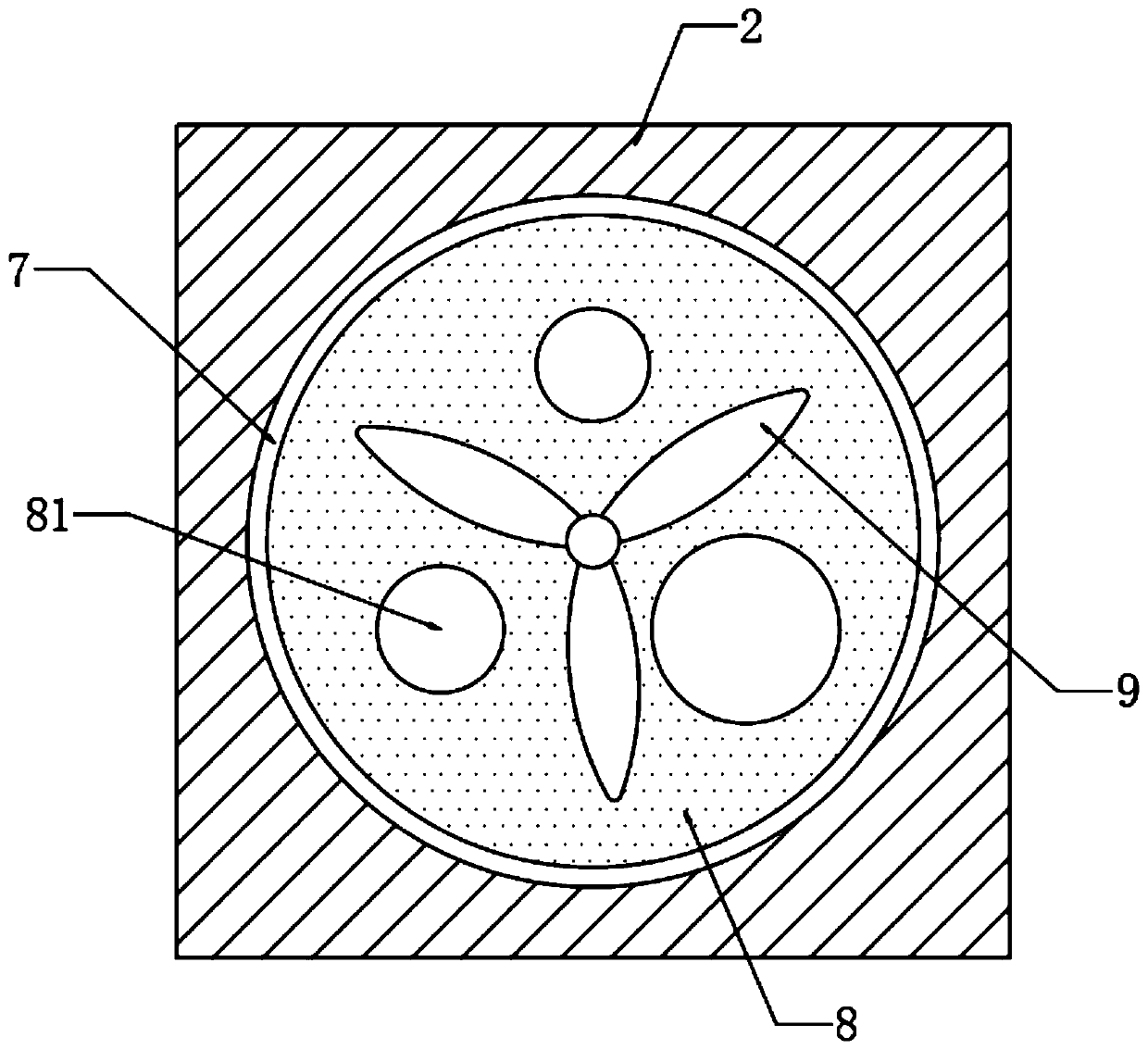
[0022] refer to Figure 1-2 , a kind of LED color lamp for building decoration, comprising a light strip 1 and a light housing 2 installed on the light belt 1, LED color lamp beads 3 are installed in the light housing 2, and a square cavity 4 is opened on the side wall of the light housing 2 , the bottom of the square cavity 4 is fixedly connected with an arc-shaped cover 5 .

[0023] It should be noted that the lower end of the arc-shaped cover 5 is in close contact with the inner bottom of the square cavity 4 and divides the square cavity 4 into two chambers that are not connected to each other, so that the arc-shaped cover 5 can be deformed under the action of air pressure.

[0024] And the arc-shaped cover 5 is made of piezoelectric ceramic material, and the two ends of the arc-shaped cover 5 are connected in series with the power supply circuit of the LED colored lamp bead 3 through a capacitor. It should be noted that the arc-shaped cover 5 is connected with the capacito...

Embodiment 2

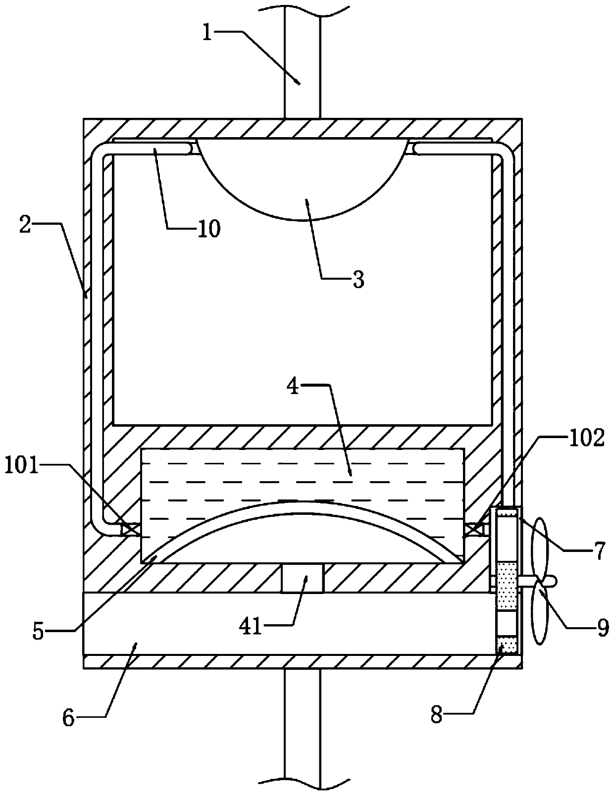
[0031] refer to image 3 , different from Embodiment 1, the square cavity 4 is filled with cooling liquid, and the cooling liquid is only located on the upper side of the arc-shaped cover 5, and the lamp housing 2 is embedded with a catheter 10, and the catheter 10 surrounds the LED The color lamp bead 3 is arranged, the water inlet end and the water outlet end of the catheter tube 10 are all communicated with the inside of the square cavity 4, and the first one-way valve 101 and the second one-way valve 101 and the second one-way valve are installed in the water inlet end and the water outlet end of the catheter tube 10 respectively. to valve 102.

[0032] It should be noted that the first one-way valve 101 only allows the cooling liquid to flow from the square chamber 4 into the catheter 10 , and the second one-way valve 102 only allows the cooling liquid to flow from the catheter 10 into the square chamber 4 .

[0033] Further, the cooling liquid in the square cavity 4 can...


PUM


Abstract

The invention discloses an LED colored lamp for building decoration. The LED colored lamp comprises a lamp strip and a lamp shell mounted on the lamp strip. LED colored lamp beads are mounted in the lamp shell. A square cavity is formed in the side wall of the lamp shell. The inner bottom of the square cavity is fixedly connected with an arc-shaped cover; the arc-shaped cover is made of piezoelectric ceramic materials, the two ends of the arc-shaped cover are connected into a power supply circuit of the LED colored lamp beads in series through capacitors, vent holes are formed in the side wallof the lamp shell, the vent holes are communicated with the square cavity through negative pressure holes, and circular grooves communicated with the vent holes are formed in the side wall of the lamp shell. According to the invention, the air velocity in the vent holes is continuously changed; the arc-shaped cover made of the piezoelectric ceramic vibrates up and down continuously, induced current is generated, the flickering lamplight change effect is finally generated, electronic equipment does not need to be mounted to control lamplight change, the structure is simple, only a simple lampbody power supply line needs to be mounted, the construction difficulty is low, energy is saved, environmental friendliness is achieved, and maintenance is convenient and easy.

Description

technical field [0001] The invention relates to the related technical field of LED lamps, in particular to an LED colored lamp for building decoration. Background technique [0002] LED lights can directly convert electrical energy into light energy. In order to pursue gorgeous lighting effects, the lamp body often emits different colors and changing lights, which are called LED lights. [0003] Among them, the function of LED lanterns used in buildings is more decorative. However, most of the existing LED lights change the light flicker frequency through electronic programs. Since the electronic programs rely on computers and other equipment to control, the installation route of the lamps and the overall equipment are relatively complicated, resulting in relatively difficult construction, large equipment footprint, and power consumption. It costs a lot, and when the equipment breaks down, it is very difficult to repair. Contents of the invention [0004] The purpose of ...

Claims


Application Information

Patent Timeline
IPC IPC(8): F21S10/06F21V23/00F21V29/56F21Y115/10
CPCF21S10/06F21V23/003F21V29/56F21Y2115/10Y02B20/72
Inventor 李明
Owner 宁波谦屹节能科技有限公司
Why Eureka
Try Eureka