Grabbing robot equipment with silicon wafer transportation and dust removal functions

A technology of silicon wafers and robots, applied in manipulators, manufacturing tools, program-controlled manipulators, etc., to prevent dust from spreading and avoid secondary pollution

Active Publication Date: 2020-09-01
盐城市聚龙湖商务集聚区发展有限公司
15 Cites 8 Cited by

AI-Extracted Technical Summary

Problems solved by technology

[0002] In industrial production, silicon wafers are widely used in the manufacture of integrated circuits. After cutting and grinding the traces on the surface, silicon wafers are etched with millions of transistors to achieve various functions, and transistors ar...

Method used

The beneficial effect of the present invention is: the present invention is carried out the mode that silicon wafer is transported after dedusting first, first silicon wafer is fixed by sucker, carries out air blowing and dedusting to silicon wafer surface by dedusting mouth, then silic...

Abstract

The invention discloses grabbing robot equipment with silicon wafer transportation and dust removal functions. The grabbing robot equipment comprises a main body, a working area is arranged outside the main body, the main body can move left and right in the working area, a linkage cavity is formed in the main body, a linkage motor is fixedly arranged in the linkage cavity, rotating rods are symmetrically arranged at the left end and the right end of the linkage motor in a power connection mode, and a driving bevel gear is fixedly arranged on the portion, located in the linkage cavity, of an outer circle face of the rotating rod on the right side. According to the equipment, a silicon wafer is transported after dust removal, the silicon wafer is fixed through a suction disc firstly, dust onthe surface of the silicon wafer is removed by blowing through a dust removal opening, the left and right ends of the silicon wafer are clamped and turned over through robot arms, dust on the back face of the silicon wafer is removed, the robot arms drive the silicon wafer to rotate in the moving process to achieve the comprehensive dust removal effect, dust diffusion is prevented through air suction of dust suction openings in the two sides, and the silicon wafer is prevented from being secondarily contaminated.

Application Domain

Programme-controlled manipulatorGripping heads +1

Technology Topic

Electric machineryWorkspace +8

Image

  • Grabbing robot equipment with silicon wafer transportation and dust removal functions
  • Grabbing robot equipment with silicon wafer transportation and dust removal functions
  • Grabbing robot equipment with silicon wafer transportation and dust removal functions

Examples

  • Experimental program(1)

Example Embodiment

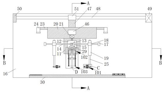
[0021] Combine below Figure 1-Figure 6 The present invention is described in detail, and for convenience of description, the orientations mentioned below are now stipulated as follows: figure 1 The up, down, left, right, front and back directions of the projection relationship itself are the same.
[0022] A robot grabbing device with the functions of transporting and removing dust for silicon wafers according to the present invention includes a main body 11, and a working area 16 is arranged outside the main body 11, and the main body 11 can move left and right in the working area 16 , the main body 11 is provided with a linkage chamber 12, and a linkage motor 13 is fixed in the linkage chamber 12. The left and right ends of the linkage motor 13 are symmetrical and the power connection is provided with a rotating rod 14, and the rotating rod 14 on the right side The outer circular surface is fixed with a driving bevel gear 15 in the linkage cavity 12, and the ends of the rotating rods 14 on the left and right sides away from the linkage motor 13 pass through the main body 11 and extend into the working area 16, The rotating rod 14 on the left and right sides is fixedly connected with a fixed block 17 at one end in the working area 16, and the sliding connection of the rotating rod 14 that can slide left and right in the working area 16 is provided with a slider 18. The front end of the block 18 is fixedly connected with a push rod 19, and the top of the main body 11 is fixedly connected with a control block 20, and a control motor 21 is arranged in the control block 20 and directly above the linkage cavity 12, and the control motor 21 It is electrically connected with the upper end of the push rod 19, the left and right ends of the control block 20 are fixedly connected with connecting rods 23, and the connecting rods 23 on both sides are fixedly connected with the ends facing away from the control block 20. The depth camera 24 at the bottom of the working area 16, the depth camera 24 shoots down to determine the position of the silicon wafer so as to control and fix the robot device 101 located below the push rod 19, the robot device 101 and the push rod 19 are fixed together. The sliding connection that can slide up and down between the rods 19 is provided with a telescopic rod 25, and the manipulator device 101 is fixedly connected to the bottom of the telescopic rod 25 and moves up and down with the telescopic rod 25. The manipulator device 101 on the left and right sides A dust removal device 103 is fixed between them. The upper end of the dust removal device 103 is fixedly connected to the bottom of the rotating device 102 located below the linkage chamber 12. The rotating device 102 includes a rotating chamber 27 with an opening downward. In the rotating cavity 27 and between the left and right walls at the lower end of the main body 11, there is a rotating block 28 which can rotate. The interlocking chamber 12 and the rotating chamber 27 extend upwards in the interlocking chamber 12 to be fixedly connected to the driven bevel gear 29 located at the lower end of the interlocking chamber 12 and meshed with the driving bevel gear 15. The lower end of the dust removal device 103 and the bottom of the working area 16 are fixed with a base 30 , and the robotic arm grabs the silicon wafer located at the left end of the base 30 and transports it to the wafer cassette located at the right end of the base 30 .
[0023]Beneficially, the inner center of the rotating block 28 is fixed with an aspirator 31, and the left and right ends of the aspirator 31 are symmetrically provided with suction pipes 32 with downward openings, and directly below the aspirator 31 is fixedly installed Lifting motor 33, the power connection of the lower end of the lifting motor 33 is provided with a screw rod 34.
[0024] Beneficially, the dust removal device 103 includes a lifting and fixing block 35 fixedly connected to the lower end of the rotating block 28, and the end of the screw 34 away from the lifting motor 33 extends downwards and penetrates through the center of the lifting and fixing block 35 The lower end of the screw 34 is fixedly connected with a screw fixing block 36, and the screw 34 is provided with a lifting rotating block 37 in a sliding connection that can slide up and down between the lifting fixing block 35 and the screw fixing block 36, The front end surface of the lifting rotating block 37 is fixedly connected with a vacuum generator 39 with an opening downward, the vacuum generator 39 is electrically connected with the control motor 21, and the lower end of the vacuum generator 39 is fixedly connected with a vacuum suction cup 40, the left and right sides of the lower end of the lifting and fixing block 35 are symmetrically fixedly connected with lifting and fixing rods 41, and the suction pipe 32 extends downwards in the rotating block 28 and passes through the lifting and fixing block 35 and the lifting and fixing The rod 41 is also provided with an air suction port 42 opening downward at the end of the lifting and fixing rod 41 .
[0025] Beneficially, an air blower 43 is fixed directly above the linkage cavity 12, and the rear blowing pipe 44 and the front blowing pipe 45 with the opening downwards are fixed in the front and back of the air blower 43, and the end of the front blowing pipe 45 is high. At the end of the rear blowing pipe 44 and above the vacuum chuck 40 .
[0026] Beneficially, a microcomputer 46 is fixed directly above the control motor 21, a sliding connecting rod 47 is fixedly connected to the upper end of the control block 20, and a sliding rod 48 is fixed above the control block 20. The power connection at the right end of the rod 48 is provided with a sliding motor 49 located at the upper right end of the work area 16 and the rotatable rotation connection at the left end is provided with a 50 located at the upper left end of the work area 16, and the upper end of the sliding connecting rod 47 is fixedly connected with a sliding connection At the lower end of 51 on the sliding rod 48, right behind the sliding rod 48, there are guide rods 52 fixedly connected at the left and right ends, and the guide rod 51 slides left and right on the sliding rod 48 and the guide rod 52.
[0027] Beneficially, the robot arm device 101 includes a linkage block 61 with an opening facing the vacuum generator 39, and the end of the linkage block 61 near the vacuum generator 39 is provided with a sliding clip cavity 53, and the sliding clip The upper and lower sides of the cavity 53 are symmetrically provided with a pulley cavity 54, and the upper and lower ends of the pulley cavity 54 are fixed with driven pulleys 55 facing the upper and lower ends of the sliding clamp cavity 53. The driven pulleys 55 on the upper and lower sides The center is fixedly connected with a pulley bar 56, and the upper and lower ends of the sliding clamp chamber 53 are symmetrical and rotatably connected to the pulley bar 56. A splint 57 that slides toward the center of the sliding clamp cavity 53 is respectively provided. In the wheel cavity 54, one end away from the sliding clamp chamber 53 is fixedly provided with a driving pulley 58, and a worm 63 is fixedly connected between the axes of the driving pulley 58 on the upper and lower sides, and the driving pulley 58 is connected to the slave A transmission belt 59 is wound between the driving pulleys 55, and a worm wheel chamber 60 is provided between the pulley chambers 54 on the upper and lower sides in the linkage block 61 and away from the end of the sliding clamp chamber 53. The worm chamber 60 A rotatable turbine 62 is fixed between the upper and lower walls, the axis of the worm 63 is engaged with the upper surface of the turbine 62, and the axis of the turbine 62 away from the sliding clamp cavity 53 is fixedly connected with a turbine rod 64 .
[0028] Beneficially, the outer surface of one end of the linkage block 61 close to the telescopic rod 25 is fixedly connected with a fixed rotary block 65, and the fixed rotary block 65 is provided with a switching cavity 66 opening toward one end of the worm wheel cavity 60. Between the upper and lower walls of the switch chamber 66 and at the end close to the telescopic rod 25 is rotatably connected with a power rod 67, and the end of the turbine rod 64 away from the turbine 62 extends into the switch chamber 66 and is connected to the power rod 66. Rod 67 is located in one end of the switch chamber 66 and is connected in rotation. The upper and lower sides of the rear end of the turbine rod 64 are symmetrically fixedly connected with an inner connection block 68. The inner wall of the end of the switch chamber 66 close to the telescopic rod 25 is located on both sides of the upper and lower sides. The symmetrical fixed connection is provided with the outer connecting block 70, and the upper and lower sides of the outer circular surface of the power rod 67 are symmetrically fixedly connected with an electromagnetic sliding block 69, and the electromagnetic sliding block 69 is provided with the inner connecting block 68 and the described inner connecting block 69. The outer connection block 70 is facing the same groove, the outer surface of the lower end of the telescopic rod 25 is fixedly connected with an electromagnetic motor 71, and the end of the power rod 67 away from the switching cavity 66 extends outward and passes through the telescopic rod 25 The lower end is power-connected with the electromagnetic motor 71 .
[0029] Beneficially, a detector 74 is fixed at the lower end of the right side of the telescopic rod 25 above the linkage block 61 , and the right end of the detector 74 is fixedly connected with the telescopic rod 25 .
[0030] Beneficially, the left and right sides of the base 30 are symmetrically provided with conveyor belts 72 located between the front and rear walls of the working area 16, the conveyor belt 72 on the left side transports silicon wafers back and forth, and the conveyor belt 72 on the right side There is a crystal box 73 that is transported back and forth.
[0031] The following combination Figure 1 to Figure 6 Describe in detail the steps of using a robot grabbing device with the functions of transporting and dedusting silicon wafers: in the initial state, the vacuum chuck 40 is located directly above the center of the base 30, and the conveyor belts 72 on the left and right sides simultaneously move the silicon wafer And the crystal box is transported to the left and right sides of the robot. The splints 57 of the robot hand devices 101 on the left and right sides are parallel to the vacuum chuck 40 and facing the direction of the vacuum chuck 40. The push rod 19 is located at an equal distance from the vacuum chuck 40 both sides.
[0032] When determining the position of the silicon wafer, the depth camera 24 starts, takes pictures of the silicon wafer on the left conveyor belt 72 below to determine the position, and transmits the information to the microcomputer 46 to obtain the distance and the vacuum that the vacuum chuck 40 will move to the left through the microcomputer 46 process. The distance that the sucker 40 moves downwards, the microcomputer 46 controls the sliding motor 49 to rotate the sliding rod 48 so as to drive the 51 to slide to the left on the sliding rod 48, and the 51 drives the robot to move to the left as a whole until the vacuum sucker 40 is located on the left conveyor belt 72. Right above the wafer, the sliding motor 49 stops, and the microcomputer 46 controls the lifting motor 33 to start rotating the screw rod 34 and then drives the lifting rotating block 37 to slide downward together with the vacuum generator 39 and the vacuum chuck 40, and the vacuum chuck 40 sucks the silicon wafer at the center. , and then rise to the original position.
[0033] At the beginning of dust removal, the blower 43 starts to discharge the pure gas at the end through the front blowing pipe 45, thereby starting to blow and remove dust on the surface of the silicon wafer sucked by the vacuum chuck 40, and the aspirator 31 starts to pass through the suction ports on the left and right sides 42 pump air around the vacuum chuck 40, discharge the dust removed from the silicon wafer by the front blowing pipe 45 through the suction port 42 to prevent the silicon wafer from being contaminated with dust again, and control the motor 21 to start and control the push rod 19 on the left and right sides to drive the telescopic rod 25 and then drive the robot hand device 101 to adjust the position and align the clip with the silicon wafer sucked by the vacuum chuck 40, the detector 74 starts to detect the thickness and position of the silicon wafer, and the microcomputer 46 processes and then controls the linkage motor 13 to start , drive the rotating rod 14 to rotate and then drive the sliders 18 on the left and right sides to move closer to the silicon wafer on the rotating rod 14, while the rotating rod 14 drives the driving bevel gear 15 to rotate and then drives the driven bevel gear 29 to rotate, and the driven bevel gear 29 drives to rotate The rod 26 rotates and then drives the rotating block 28 to rotate in the rotating chamber 27, the upper end of the lifting fixed block 35 is fixedly connected with the lower end of the rotating block 28, and then the rotating block 28 drives the lifting fixed block 35 to rotate, and the lifting fixed block 35 drives the vacuum suction cup 40 to rotate and be vacuumed The silicon wafer sucked by the suction cup 40 rotates, and the front blowing pipe 45 remains motionless and continues to maintain the blowing state to carry out screw fixing on the rotating silicon wafer. The electromagnetic motor 71 controls the electromagnetic sliding block 69 to move towards the linkage block 61 so that the electromagnetic sliding block 69 is engaged with the inner connection block 68, and then drives the turbine 62 to rotate by rotating the turbine rod 64, and the turbine 62 drives the worm 63 to rotate, and the worm 63 Drive the vertically symmetrical driving pulley 58 to rotate and then drive the driven pulley 55 to drive the pulley bar 56 to rotate through the transmission belt 59, and the pulley bar 56 drives the up and down symmetrical splint 57 to adjust the thickness of the silicon wafer, and the slide block 18 continues to the center. Move until the left and right ends of the silicon wafer are located between the upper and lower clamping plates 57, and the clamping plates 57 move to the center to clamp the silicon wafer.
[0034] When overturning, the vacuum generator 39 stops, the silicon wafer is no longer sucked by the vacuum chuck 40, the control motor 21 controls the push rod 19 and then drives the telescopic rod 25 and the robot arm device 101 to move downward, thereby driving the silicon wafer to move downward, and the electromagnetic The motor 71 controls the electromagnetic sliding block 69 to move towards the direction close to the telescopic rod 25, and then engages with the inner wall of the fixed rotating block 65, the turbine rod 64 remains fixed and no longer rotates, and the power rod 67 drives the fixed rotating block 65 to rotate, thereby driving the entire linkage block 61 to rotate , the left and right side linkage blocks 61 rotate to drive the silicon wafer clamped in the middle to turn over, the rear air blowing pipe 44 starts and the front air blowing pipe 45 simultaneously dedusts the silicon wafer, and the control motor 21 controls the push rod 19 to drive the telescopic rod 25 to move the manipulator device 101 Reset, the vacuum generator 39 starts to suck the silicon wafer through the vacuum chuck 40, the rear air blowing pipe 44 stops, the front air blowing pipe 45 removes dust from the back of the silicon wafer, and the linkage motor 13 starts to drive the sliders 18 on both sides to move to the outer ends of both sides , and then drive the driven bevel gear 29 through the driving bevel gear 15 to drive the silicon wafer below to rotate, so that the front blowing pipe 45 can remove the dust from the screw fixing block 3 worm wheel cavity at 60 degrees on the back of the silicon wafer, and the suction port 42 keeps dust suction all the time. state.
[0035] Continue to keep the dust removal and vacuuming state during transportation, the depth camera 24 on the right starts to take pictures of the bottom to determine the position of 73, the sliding motor 49 starts to drive 51 to move to the right and then drives the silicon wafer to move to the top of the right 73, when the rear blowing pipe 44 is located When above 73, after blower 43 starts, air blowing pipe 44 carries out dust removal to 73, slide block 18 moves to vacuum chuck 40, repeats the action of silicon wafer rotation and dust removal, splint 57 clamps and turns over silicon wafer to make it face up, and then the machine The hand device 101 rises and the vacuum chuck 40 sucks the silicon wafer, the slide block 18 moves to the outer end, and the front of the silicon wafer is again dust-removed by the screw fixing block 3 and the worm gear chamber at 60 degrees, and the lifting motor 33 is started to drive the silicon wafer to move downward until the silicon wafer is placed into 73, 73 is sealed, and then the next silicon wafer is dedusted and transported.
[0036] The beneficial effect of the present invention is that: the present invention firstly fixes the silicon wafer by the suction cup through the method of firstly removing dust from the silicon wafer, then blows and removes dust on the surface of the silicon wafer through the dust removal port, and then uses the robot hand to move the silicon wafer to the left and right sides. The silicon wafer is flipped by clamping at the end, and then dust is removed on the back of the silicon wafer. During the movement of the robot, the silicon wafer is driven to rotate to achieve an all-round dust removal effect. The dust suction ports on both sides prevent dust from spreading by sucking air, and avoid secondary pollution of the silicon wafer.
[0037] Through the above methods, those skilled in the art can make various changes according to the working modes within the scope of the present invention.

PUM

no PUM

Description & Claims & Application Information

We can also present the details of the Description, Claims and Application information to help users get a comprehensive understanding of the technical details of the patent, such as background art, summary of invention, brief description of drawings, description of embodiments, and other original content. On the other hand, users can also determine the specific scope of protection of the technology through the list of claims; as well as understand the changes in the life cycle of the technology with the presentation of the patent timeline. Login to view more.

Similar technology patents

Filtering device for nitrile rubber material manufacturing

InactiveCN112024390Aeasy to filterprevent dust from spreading
Owner:湖南洋韬材料科技有限公司

Feeding mechanism for cellular network particle feeding machine

InactiveCN105621077Aevenly distributedprevent dust from spreading
Owner:SUZHOU PULISEN MACHINERY

Fixed grain distributor of grain dryer

PendingCN111453472Aprevent dust from spreadingGuaranteed position
Owner:安徽金谷机械科技有限公司

Piling device for building constructional engineering foundation

InactiveCN111851489Areduce noise pollutionprevent dust from spreading
Owner:山东鼎鲁建筑工程有限公司

Efficient coaxial air curtain dedusting system for coal mine

InactiveCN104612745Aprevent dust from spreadingGood dust removal effect
Owner:安徽惠尔矿用设备有限公司

Classification and recommendation of technical efficacy words

  • prevent dust from spreading
  • avoid secondary pollution

Efficient coaxial air curtain dedusting system for coal mine

InactiveCN104612745Aprevent dust from spreadingGood dust removal effect
Owner:安徽惠尔矿用设备有限公司

Piling device for building constructional engineering foundation

InactiveCN111851489Areduce noise pollutionprevent dust from spreading
Owner:山东鼎鲁建筑工程有限公司

Feeding mechanism for cellular network particle feeding machine

InactiveCN105621077Aevenly distributedprevent dust from spreading
Owner:SUZHOU PULISEN MACHINERY

Filtering device for nitrile rubber material manufacturing

InactiveCN112024390Aeasy to filterprevent dust from spreading
Owner:湖南洋韬材料科技有限公司

Fixed grain distributor of grain dryer

PendingCN111453472Aprevent dust from spreadingGuaranteed position
Owner:安徽金谷机械科技有限公司

Device technology configuration method for treating house refuses by using rotary cement kiln

InactiveCN102070308AAvoid secondary synthesisavoid secondary pollution
Owner:CITIC HEAVY INDUSTRIES CO LTD +1

Aquaculture wastewater treatment process

Owner:河南恒野农牧股份有限公司
Why Eureka
Try Eureka