Modular design gearbox and gear implementation method

A technology of modular design and implementation method, applied in the field of gearboxes, can solve problems such as increased production costs, reduced efficiency, and fewer gears, and achieve reduced production costs and use costs, short transmission paths, and wide speed ratio ranges Effect

Active Publication Date: 2020-09-01
JIANGSU ADVANCED CONSTR MASCH INNOVATION CENT LTD +1
View PDF6 Cites 1 Cited by
  • Summary
  • Abstract
  • Description
  • Claims
  • Application Information

AI Technical Summary

Problems solved by technology

[0004] For some main engines such as loaders, they only perform the shoveling operation cycle of forward 2 gears, forward 1 gears and reverse 2 gears in a small area. Too many gears will lead to cumbersome operations and lower efficiency. There is a demand for fewer gears for the gearbox. If the multi-gear gearbox suppresses the combination of some clutches to achieve fewer gears, the actual number of parts will not be reduced, which will cause unnecessary waste.
Redesigning and developing a new structure of less-gear gearbox will not only increase the design cost, but also it is difficult to ensure the commonality with the original multi-gear gearbox components, resulting in increased production costs
[0005] On the other hand, gearboxes in the field of construction machinery are divided into two types: planetary gearboxes and fixed-shaft gearboxes according to the form of gear trains. The former planetary gearbox has a compact structure and requires less space, but has a complex structure and higher precision requirements. The fixed-shaft gearbox has a simple structure design and is easy to realize variable gear numbers and gear ratios. It has strong adaptability, is convenient to manufacture and maintain, and can meet The requirements for flexibility and modularization of construction machinery gearboxes are the development trend of the high-end market for construction machinery in the future

Method used


Image

  • Modular design gearbox and gear implementation method
  • Modular design gearbox and gear implementation method
  • Modular design gearbox and gear implementation method

Examples


Embodiment Construction

[0064] Exemplary embodiments of the present invention are described below in conjunction with the accompanying drawings, which include various details of the embodiments of the present invention to facilitate understanding, and they should be regarded as exemplary only. Accordingly, those of ordinary skill in the art will recognize that various changes and modifications of the embodiments described herein can be made without departing from the scope and spirit of the invention. Also, descriptions of well-known functions and constructions are omitted in the following description for clarity and conciseness.

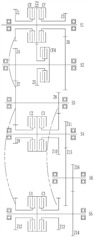
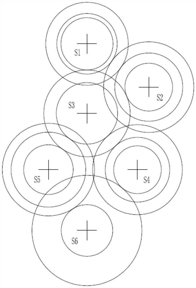
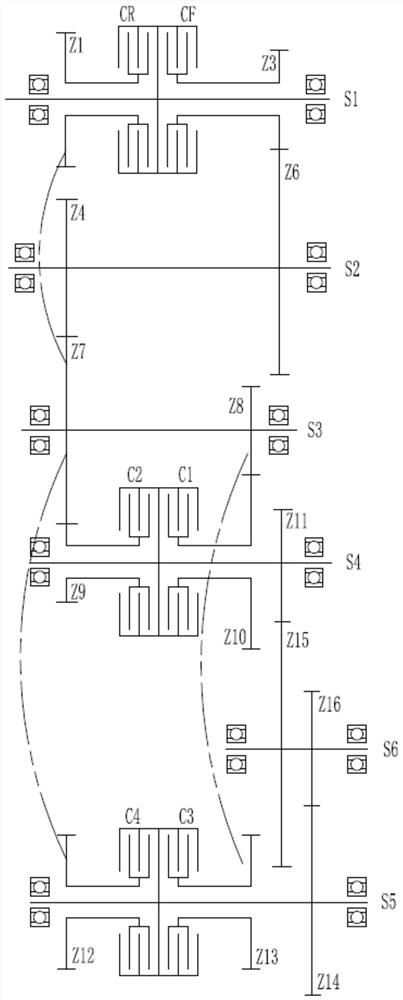
[0065] see figure 1 and figure 2 , a modular design gearbox, including a box body, and also includes a drive shaft S1, an intermediate shaft S2, an intermediate shaft S3, an intermediate shaft S4, an intermediate shaft S5, and an output shaft S6; the drive shaft S1 is provided with a fixed gear Z2, through The floating gear Z1 installed by the clutch CR and the floating...


PUM


Abstract

The invention relates to a modular design gearbox and a gear implementation method. The gearbox comprises a box body, a driving shaft, four middle shafts and an output shaft. The gearbox is of a six-shaft layout. The driving shaft S1, the middle shaft S4 and the middle shaft S5 are each provided with two clutch bags, and the middle shaft S2 is provided with one clutch bag. By means of the structure, the transmission path is short, and stability is better. By means of the six shafts and the seven clutches, the gearbox can achieve the mode of up to 8 forwarding gears and 4 backward gears, the speed ratio range is wide, and the gearbox can be adjusted flexibly, the less-gear mode can be achieved by reducing part of components, modularization is achieved, universality is improved, and the production cost and using cost of the gearbox are reduced. Meanwhile, the forwarding gear is achieved by combining two clutches and conducting gear engagement four times, the backward gear is achieved bycombining two clutches and conducting gear engagement three times, the transmission path is short, and reliability is high.

Description

technical field [0001] The invention relates to the technical field of gearboxes, in particular to a modular design gearbox and a gear realization method. Background technique [0002] There are many types of main engine products of construction machinery and the demand for a single type is relatively small. It is not realistic to design and develop gearboxes for various main engines. This requires that the gearboxes applied to construction machinery can cover a variety of products with similar power ranges. The working conditions of main engine products are complex, and the number of gears and transmission ratio requirements are also different, which puts forward higher requirements on the number of gears and the flexibility of gear ratios and the versatility of parts of construction machinery gearboxes. [0003] For the main engine with multi-gear requirements, customers have higher and higher requirements for product smoothness, which requires the gearbox to have more g...

Claims


Application Information

Patent Timeline
Patent Type & Authority Applications(China)
IPC IPC(8): F16H3/093
CPCF16H3/093F16H3/006F16H2200/0043F16H2200/006F16H2200/0095F16H2200/2048B60Y2200/22
Inventor 詹东安吕昌闫伟朋石国国张刚
Owner JIANGSU ADVANCED CONSTR MASCH INNOVATION CENT LTD
Why Eureka
Try Eureka