Power wire alarm device

A technology of alarm devices and wires, which is applied in the direction of measuring devices, measuring current/voltage, measuring electrical variables, etc., can solve problems that are prone to failure, alarm devices do not have moisture-proof, dust-proof, high-temperature protection, power transmission, etc., to improve safe use Lifespan, practical effect

Pending Publication Date: 2020-09-01
SHENZHEN CHOSEAL IND +1
View PDF0 Cites 2 Cited by
  • Summary
  • Abstract
  • Description
  • Claims
  • Application Information

AI Technical Summary

Problems solved by technology

[0003] Electric power is usually transmitted through wires, so the use status of wires often plays a decisive role in power transportation. Nowadays, people generally install alarm devices on the power grid to detect the use status of wires in real time, but the existing alarm devices do not It has the functions of moisture-proof, dust-proof and high-temperature resistance. During use, it is easy to break down and cause problems in power transmission. Therefore, the present invention proposes a power wire alarm device to solve the above problems

Method used


Image

  • Power wire alarm device
  • Power wire alarm device
  • Power wire alarm device

Examples


Embodiment 1

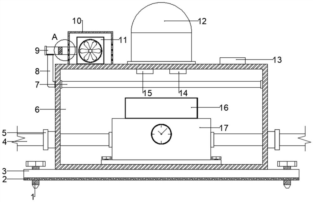
[0021] see Figure 1~3 , in an embodiment of the present invention, a power wire alarm device includes a mounting plate 3 and a box body 6, the box body 6 is fixed on the mounting plate 3, and a current device 17 is fixedly installed in the box body 6, and the current device 17 There is a power line input terminal and a power line output terminal on the top, and the left and right side walls of the box body 6 are provided with a line port 5 for connecting the electric wire 4 to the current device 17, and the top of the box body 6 is fixed with a warning light 12 And buzzer 13, wherein the lampshade of warning lamp 12 is made of PVC material, and light transmission is better and light in weight.

[0022] A temperature sensor 14 and a humidity sensor 15 are fixedly installed on the top of the inner cavity of the box body 6. A plurality of air outlet pipes 7 are equidistantly arranged in the box body 6 from front to back, and a plurality of air outlet pipes 7 are equidistantly ar...

Embodiment 2

[0027] The difference between the embodiment of the present invention and embodiment 1 is that, further, since the device is usually used outdoors and exposed to wind and sun for a long time, in order to prevent the device from being oxidized too quickly, the mounting plate 3 and the box body 6 are coated with an anti-oxidation coating, which can effectively slow down the oxidation process of the device and further prolong its service life.

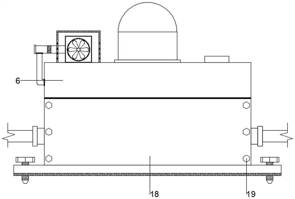
[0028] The working principle of the present invention is: when the present invention is in use, the device is first fixedly installed on the installation point by a plurality of installation bolts 1, then the cover plate 18 is opened to connect the electric wire 4 to the current device 17, after installation, Then close the cover plate 18 and tighten the hexagonal screws 19 in sequence. When the galvanometer 17 detects that the current is abnormal or there is no current, the galvanometer 17 transmits the signal to the signal receiver, and ...


PUM


Abstract

The invention discloses a power wire alarm device. The device comprises a mounting plate and a box body; the box body is fixedly arranged on the mounting plate; a current device is fixedly arranged inthe box body; a warning lamp and a buzzer are fixedly arranged at the top of the box body; a temperature sensor and a humidity sensor are fixedly mounted at the top of the cavity of the box; a plurality of air outlet pipes are equidistantly arranged in the box body from front to back; a small fan is fixedly mounted at the top of the box body through a bracket; the output end of the small fan is connected with a main air guide pipe in a sealed mode. The end, away from the small draught fan, of the main air guide pipe is connected with branch air guide pipes with the same number as the air outlet pipes. The device has the advantages that the moisture-proof, dust-proof and high-temperature-proof functions are realized, internal components can be effectively protected in the long-time use process, the safety service life of the device is greatly prolonged, and the practicability is realized.

Description

technical field [0001] The invention relates to the technical field of power devices, in particular to a power wire alarm device. Background technique [0002] Electricity is an energy powered by electric energy. It was invented in the 1870s. The invention and application of electricity set off the second industrialization climax. Since then, technology has changed people's lives. Even in today's Internet age, we still have a continuous growth in electricity. Because we have invented more products that use electricity, such as computers and home appliances, it is undeniable that the continuous emergence of new technologies has made electricity a necessity for people; the large-scale power system that appeared in the 20th century is one of the most important achievements in the history of human engineering science First, it is mainly a power production and consumption system composed of power generation, power transmission, power transformation, power distribution and power c...

Claims


Application Information

Patent Timeline
IPC IPC(8): G01R19/165G01D21/02
CPCG01D21/02G01R19/165
Inventor 孙梓超
Owner SHENZHEN CHOSEAL IND
Why Eureka
Try Eureka