Saw chain of felling saw

A technology for logging saws and saw chains, applied in the field of electric logging saws, can solve the problems of prone to strain, reduced shear resistance of rivets, hidden safety hazards, etc., achieve excellent shear resistance, ensure firmness and safety performance, and improve The effect of firmness

Active Publication Date: 2016-09-28
江门市锦汉实业有限公司
View PDF8 Cites 1 Cited by
  • Summary
  • Abstract
  • Description
  • Claims
  • Application Information

AI Technical Summary

Problems solved by technology

[0002] The sawing chain of the existing common logging saw includes a connecting chain link, a left cutting chain link and a right cutting chain link, and the left cutting chain link and the right cutting chain link are arranged alternately, and the adjacent left cutting chain link and the right cutting chain link There is a connecting chain link between them, and the adjacent chain links are connected by driving pieces and rivets; the general cutting chain link includes two connecting pieces, one of which is integrally connected with a generally L-shaped cutting blade, And the end of the blade at the front end of the cutting blade protrudes slightly forward. At the moment when the blade contacts the object to be c

Method used


Image

  • Saw chain of felling saw
  • Saw chain of felling saw
  • Saw chain of felling saw

Examples


Example Embodiment

[0040] Example 1

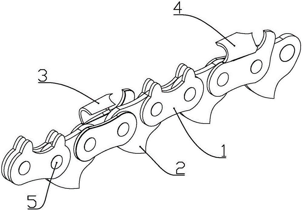
[0041] according to Figure 1 to Figure 12 As shown, this embodiment is a saw chain of a felling saw, including a connecting link 1 and a cutting link connected by a driving piece 2, and the driving piece is connected with the connecting link and the cutting link respectively through rivets Rotatingly connected, the cutting links include a left cutting link 3 and a right cutting link 4 that are alternately arranged.

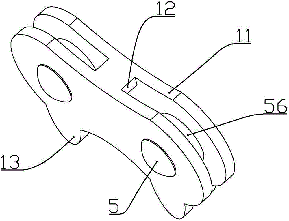
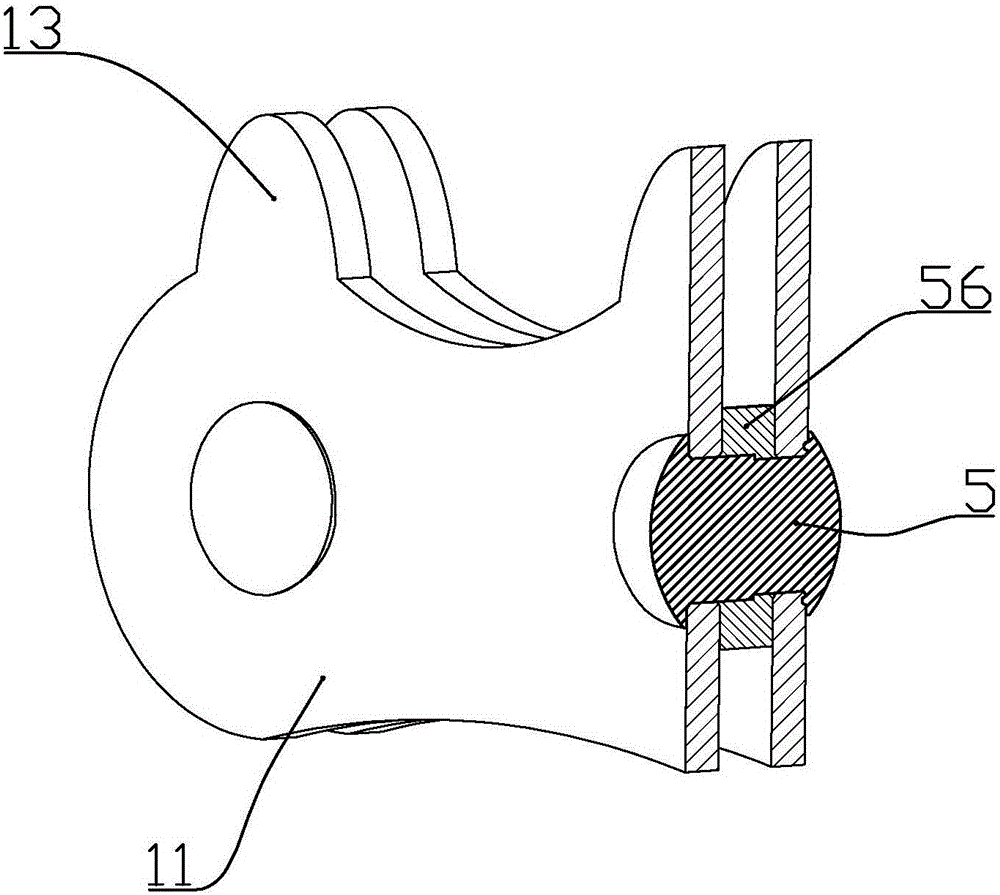
[0042] The connecting link is composed of two connecting pieces 11 and a connecting portion 12 integrally connected to the middle side in the length direction of the two connecting pieces. The connecting link is formed by stamping a complete metal sheet; There are two large connecting holes 62, and two small connecting holes 61 are opened at the positions corresponding to the two large connecting holes on the other connecting piece, and the diameter of the small connecting holes is smaller than that of the large connecting holes; A chamfer...

Example Embodiment

[0055] Example 2

[0056] combine Figure 5 to Figure 15 As shown, this embodiment is a saw chain of a felling saw, including a connecting link 1 and a cutting link connected by a driving piece 2, and the driving piece is connected with the connecting link and the cutting link respectively through rivets Rotatingly connected, the cutting links include a left cutting link 3 and a right cutting link 4 that are alternately arranged.

[0057] The connecting link is composed of two connecting pieces 11 and a connecting portion 12 integrally connected to the middle side in the length direction of the two connecting pieces. The connecting link is formed by stamping a complete metal sheet; There are two large connecting holes 62, and two small connecting holes 61 are opened at the positions corresponding to the two large connecting holes on the other connecting piece, and the diameter of the small connecting holes is smaller than that of the large connecting holes; A chamfer is f...


PUM

PropertyMeasurementUnit
Hardnessaaaaaaaaaa
Hardnessaaaaaaaaaa

Abstract

The invention discloses a saw chain of a felling saw. The saw chain comprises connecting chain links and cutting chain links connected through driving pieces, wherein the driving pieces are rotatably connected with the connecting chain links and the cutting chain links through rivets; the cutting chain links comprise left cutting chain links and right cutting chain links which are arranged in turns; the left cutting chain links comprise main connecting pieces, sub connecting pieces, connection parts connected between the main connecting pieces and the sub connecting pieces, cutting blades connected on the sides, away from the connection parts, on the main connecting pieces, and limiting heads which are integrally connected on the main connecting pieces and are positioned at the front of the cutting blades; notches are reserved between the limiting heads and the cutting blades; and the left cutting chain links are formed through stamping a complete metal piece. According to the saw chain, the structure is ingenious, the strength is high, the cutting speed is high, and the service life is relatively long.

Description

technical field [0001] The invention belongs to the field of electric logging saws, and in particular relates to a chain structure of the logging saw. Background technique [0002] The sawing chain of the existing common logging saw includes a connecting chain link, a left cutting chain link and a right cutting chain link, and the left cutting chain link and the right cutting chain link are arranged alternately, and the adjacent left cutting chain link and the right cutting chain link There is a connecting chain link between them, and the adjacent chain links are connected by driving pieces and rivets; the general cutting chain link includes two connecting pieces, one of which is integrally connected with a generally L-shaped cutting blade, And the end of the blade at the front end of the cutting blade protrudes slightly forward. At the moment when the blade contacts the object to be cut, the cutting blade is subjected to a force opposite to the cutting direction, and a comp...

Claims


Application Information

Patent Timeline
IPC IPC(8): B27B33/14
CPCA01G3/086A01G23/091B27B17/00B27B33/14B27B33/142
Inventor 林建伟潘星星
Owner 江门市锦汉实业有限公司
Why Eureka
Try Eureka