
UHF waveband omnidirectional shadow-hiding antenna

An antenna and concealment technology, which is applied in the direction of antenna, antenna support/installation device, antenna grounding switch structure connection, etc., can solve the problem of low probability of radar backlobe interference rejection, optimize the synthetic beam coverage performance, optimize the maximum beam Directional, structured and compact effect

Pending Publication Date: 2020-09-01
CHINA ELECTRONICS TECH GRP CORP NO 14 RES INST
View PDF0 Cites 0 Cited by
  • Summary
  • Abstract
  • Description
  • Claims
  • Application Information

AI Technical Summary

Problems solved by technology

[0003] In modern warfare, the UHF band (Ultra High Frequency) refers to the frequency range of 300-1000MHz, and the wavelength is 0.3-1m. This band is not easily affected by the weather due to its strong target reflection characteristics, low external noise, and small path atmospheric loss. and other advantages, it is very suitable for anti-stealth intelligence radar. The conventional invisible antenna design selects several antenna elements from the main antenna and synthesizes them as a hidden beam. Although this method is simple, it has a low probability of radar backlobe interference rejection. question

Method used


Image

  • UHF waveband omnidirectional shadow-hiding antenna
  • UHF waveband omnidirectional shadow-hiding antenna
  • UHF waveband omnidirectional shadow-hiding antenna

Examples


Embodiment Construction

[0029] The following will clearly and completely describe the technical solutions in the embodiments of the present invention with reference to the accompanying drawings in the embodiments of the present invention. Obviously, the described embodiments are only some, not all, embodiments of the present invention. Based on the embodiments of the present invention, all other embodiments obtained by persons of ordinary skill in the art without making creative efforts belong to the protection scope of the present invention.

[0030] In the description of the present invention, it should be noted that, unless otherwise specified and limited, the terms "installed", "set with", "sleeved / connected", "connected", etc. should be understood in a broad sense, such as " Connection" can be a fixed connection, a detachable connection, or an integral connection; it can be a mechanical connection or an electrical connection; it can be a direct connection or an indirect connection through an inte...


PUM


Abstract

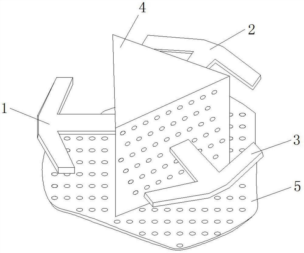
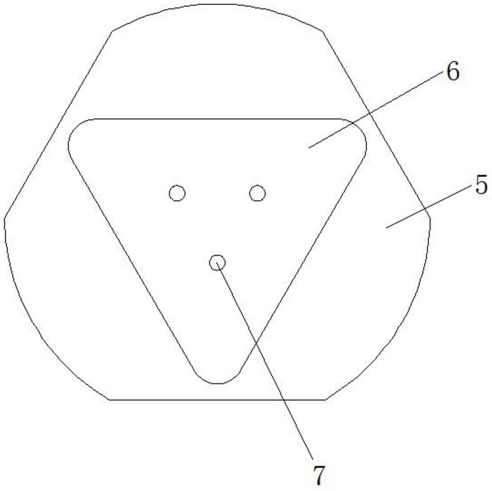
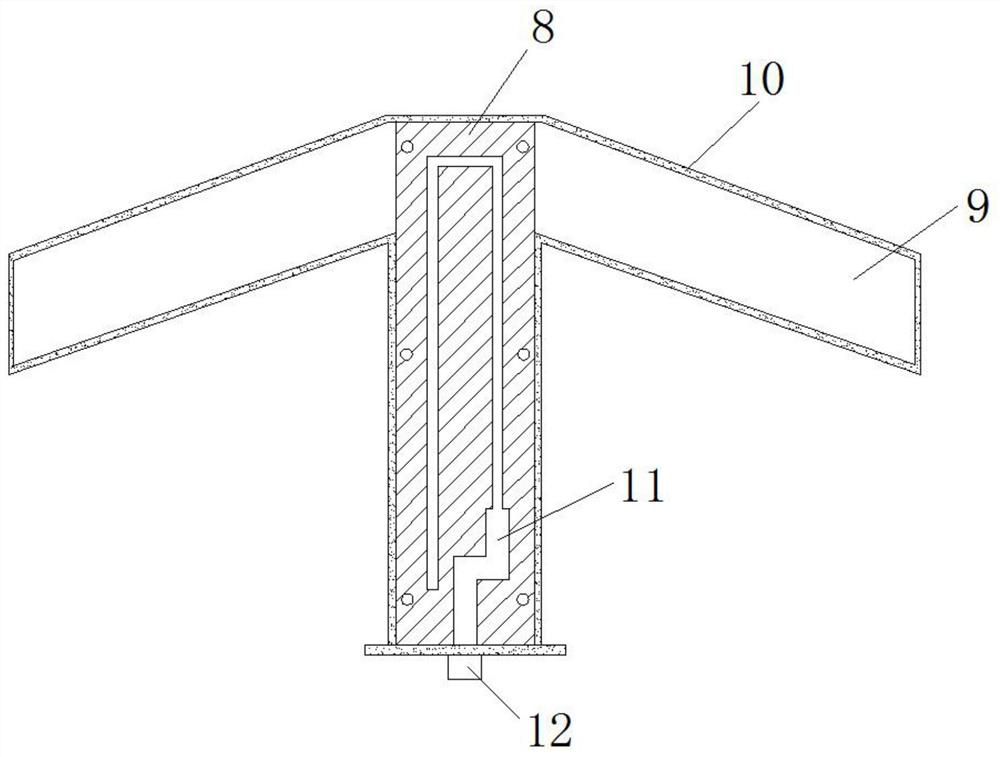
The invention discloses a UHF waveband omnidirectional shadow-hiding antenna. The invention relates to the technical field of microwave antennas. The antenna comprises a dipole antenna body and a structural framework, the dipole antenna body is composed of three oscillator antennas which form included angles of 120 degrees. The oscillator antennas and the structural framework are interconnected through screws. The structural framework is welded and interconnected with the reflection plane; the oscillator antennas are interconnected with three connectors on the flange base through three radio frequency cables; the structure is complete and compact, firm and durable, simple in form and easy to install and maintain; by optimizing the triangular side length size of the structural framework andthe size of the reflection plane, the included angle reflector formed by the structural framework and the reflection plane can be adjusted, so that the maximum beam pointing direction of the oscillator antennas on the pitching plane is optimized, and the synthetic beam coverage performance of the three oscillator antennas in the whole airspace is optimized; wave beams formed by the three oscillator antennas respectively cover a 120-degree airspace, and amplitude fluctuation at the overlapping position of the three wave beams in an azimuth plane is optimized and can be smaller than + / -2dB.

Description

technical field [0001] The invention relates to the technical field of microwave antennas, in particular to an omnidirectional invisible antenna in the UHF band. Background technique [0002] With the complex and diversified development of electronic countermeasures technology in modern warfare, the requirements for anti-jamming capability in the field of radar technology are also getting higher and higher. The strength of anti-jamming capability directly determines the survivability of radar in the battlefield. The invisible antenna is a typical application method to improve the anti-jamming ability of the radar. Its working principle is to obtain a set of side lobe amplitudes 3-5dB higher than that of the main antenna in a certain airspace (usually the azimuth omnidirectional airspace within the specified range of elevation angle). The hidden shadow beam, through the amplitude comparison between the two beams, removes the false target interference in the side lobe area of ...

Claims


Application Information

Patent Timeline
Patent Type & Authority Applications(China)
IPC IPC(8): H01Q1/36H01Q1/12H01Q1/50H01Q15/14H01Q5/50H01Q5/378
CPCH01Q1/36H01Q1/12H01Q1/50H01Q15/14H01Q5/50H01Q5/378
Inventor 王真孙磊王侃于大群郭志宏张洪银
Owner CHINA ELECTRONICS TECH GRP CORP NO 14 RES INST
Learn More