Precision voltage sampling circuit and sampling method

A voltage sampling and voltage dividing circuit technology, which is applied in the direction of electrical components, output power conversion devices, etc., can solve problems such as poor anti-interference performance of the circuit, decrease in voltage sampling accuracy, and affect measurement results, so as to enhance anti-interference ability, The effect of suppressing temperature drift and improving sampling accuracy

Pending Publication Date: 2020-09-01
JIANGSU GTAKE ELECTRIC CO LTD
View PDF0 Cites 6 Cited by
  • Summary
  • Abstract
  • Description
  • Claims
  • Application Information

AI Technical Summary

Problems solved by technology

[0004] However, when the input of the above-mentioned differential amplifier circuit is a strong electric signal and the output is a weak electric signal, the insulation resistance between the strong and weak electric currents is connected in parallel with the resistor 1 and the resistor 2 in the circuit, so the values ​​of the resistor 1 and the resistor 2 must be In addition, when a small voltage signal is input, the existence of the bias current of the integrated operational amplifier will make the voltage sampling accuracy of the circuit At the same time, limited by the resolution of the A / D converter, the voltage sampling accuracy of the circuit will further decrease, and there is no input voltage limiting component, it is easy to make the input voltage too large, making the integrated operational amplifier work at Non-linear region, causing the output voltage to be constant and affecting the measurement results

Method used


Image

  • Precision voltage sampling circuit and sampling method
  • Precision voltage sampling circuit and sampling method
  • Precision voltage sampling circuit and sampling method

Examples


Embodiment 1

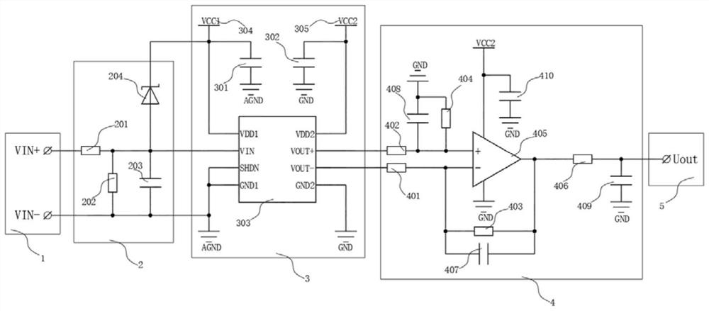
[0044] see figure 1 , comprising a voltage input terminal 1, a voltage divider circuit 2, an isolated operational amplifier circuit 3, a differential amplifier circuit 4 and a voltage output terminal 5, the voltage input terminal 1 and the input terminal of the voltage divider circuit 2 are electrically connected, and the voltage divider The negative pole of circuit 2 is electrically connected to the analog ground.

[0045] The isolated operational amplifier circuit 3 includes a second filter capacitor 301, a third filter capacitor 302, an isolation amplifier 303, an input power supply 304 and an output power supply 305, and the input terminal of the isolation amplifier 303 is connected to the voltage divider circuit 2, The input power supply of the isolation amplifier 303 is electrically connected to the input power supply 304, one end of the second filter capacitor 301 is electrically connected to the input power supply 304 and the other end is electrically connected to the...


PUM


Abstract

The invention discloses a precision voltage sampling circuit and a sampling method. The circuit comprises a voltage input end, a voltage division circuit, an isolation operational amplification circuit, a differential amplification circuit and a voltage output end. The voltage input end is electrically connected with the input end of the voltage division circuit, the negative electrode of the voltage division circuit is electrically connected with the analog ground, the isolation operational amplifier circuit comprises an isolation amplifier, an input end power supply and an output end power supply, and the input end of the isolation amplifier is connected with the voltage division circuit; the isolation amplifier is introduced, so that the sampling circuit has a good input and output ohmic isolation characteristic, the anti-interference capability is enhanced, and signals can be transmitted with high impedance and high common-mode rejection capability in a noise environment; by adopting the differential amplification circuit, the amplification capability of a differential mode signal and the inhibition capability of a common mode signal are improved, the common mode rejection ratio is effectively improved, the temperature drift can be better inhibited, and different voltage division modes are adopted according to the range of the voltage to realize the segmented sampling of the input voltage.

Description

technical field [0001] The invention relates to the technical field of voltage detection, in particular to a precision voltage sampling circuit and a precision voltage sampling method. Background technique [0002] In a high-voltage DC-DC converter, a non-isolated differential amplifier circuit is usually used for feedback sampling of the DC output voltage. For details, see image 3 , is a simple differential amplifier circuit commonly used in the prior art, specifically: the negative pole (VIN-) of the input terminal is connected to the reverse input terminal of the integrated operational amplifier, a resistor 1 is connected in series between the two, and the positive pole of the input interface ( One end of VIN+) is connected to the non-inverting input terminal of the integrated operational amplifier, and resistor two is connected in series between the two, and the two ends of resistor three are respectively connected to the inverting input terminal and output terminal of t...

Claims


Application Information

Patent Timeline
Patent Type & Authority Applications(China)
IPC IPC(8): H02M1/00
CPCH02M1/00H02M1/0003H02M1/0009
Inventor 高鑫
Owner JIANGSU GTAKE ELECTRIC CO LTD
Why Eureka
Try Eureka