Supercharge Your Innovation With Domain-Expert AI Agents!

Method and device for evaluating angular position of object, and driver assistance system

An angular position and object technology, applied in the field of driver assistance systems, can solve problems such as huge computational overhead, and achieve the effects of reducing energy consumption, reducing computational overhead, and fast object detection

Pending Publication Date: 2020-09-01
ROBERT BOSCH GMBH
View PDF1 Cites 0 Cited by
  • Summary
  • Abstract
  • Description
  • Claims
  • Application Information

AI Technical Summary

Problems solved by technology

[0006] However, especially in the case of large angular ranges and high object resolutions (which enable the detection of weaker objects as well), the computational overhead for angle estimation can be enormous

Method used


Image

  • Method and device for evaluating angular position of object, and driver assistance system
  • Method and device for evaluating angular position of object, and driver assistance system
  • Method and device for evaluating angular position of object, and driver assistance system

Examples


Embodiment Construction

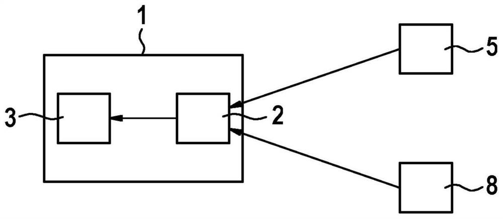
[0037] figure 1 A schematic block diagram of a device 1 for evaluating the angular position of an object that has been identified from radar data is shown. Device 1 includes an interface 2 , which is coupled to a radar device 5 of the vehicle and receives radar data therefrom. The radar device 5 is preferably designed as a MIMO radar device. In particular, the radar device can emit different frequency ramps in a time-division multiplexing method, for example according to the method disclosed in US 20170131392 A1. By flexibly choosing the modulation method, the distance and relative velocity of objects can be uniquely and unambiguously determined without tracking over multiple cycles.

[0038] Interface 2 is also coupled to a sensor device 8 of the vehicle, which is designed to measure the intrinsic speed of the vehicle. The measured intrinsic speed is transmitted to the device 1 via the interface 2 .

[0039] The device 1 also has a computing device 3 which further ...


PUM


Abstract

The invention relates to a method for evaluating the angular position of an object (7) which is detected using radar data, said radar data being ascertained by a radar device (5), having the steps of:ascertaining (S1) the speed (v_ego) of the radar device (5); ascertaining (S2) the speed (v_rel) of the detected object (7) relative to the radar device (5) using the ascertained radar data; ascertaining (S3) at least one angular scanning range (alpha, beta) using the ascertained speed (v_ego) and the ascertained relative speed (v_rel), wherein the at least one angular scanning range (alpha, beta) corresponds to possible stationary objects (7) which have a relative speed (v_rel) that substantially corresponds to the ascertained relative speed (v_rel); and ascertaining (S4) whether the azimuthangle of the detected object (7) lies in the ascertained angular scanning range (alpha, beta).

Description

technical field [0001] The invention relates to a method for evaluating the angular position of an object identified from radar data and to a corresponding device. Furthermore, the invention relates to a driver assistance system for a vehicle. Background technique [0002] In addition to calculating distances and relative speeds, the azimuth and elevation of objects can also be determined from radar data. These measured variables can be evaluated by driver assistance systems in order to control certain vehicle functions. Depending on the elevation angle, it is further possible to detect whether an object can be driven over, towards each other or under it. In particular for the lane assignment of objects, the angle of the objects must be precisely determined. [0003] In addition to conventional radar devices, multiple-input multiple-output (MIMO) radar devices with multiple transmit and receive antennas are known. With the increased virtual aperture of the overall array ...

Claims


Application Information

Patent Timeline
Patent Type & Authority Applications(China)
IPC IPC(8): G01S13/58G01S13/46G01S13/931
CPCG01S13/46G01S13/58G01S2013/932H04B17/309B60W40/00G01S7/4021G01S13/589G01S13/72B60W2420/408
Inventor B·勒施
Owner ROBERT BOSCH GMBH
Features
  • R&D
  • Intellectual Property
  • Life Sciences
  • Materials
  • Tech Scout
  • Unparalleled Data Quality
  • Higher Quality Content
  • 60% Fewer Hallucinations
Learn More