
Construction waste crushing device capable of crushing large amount of construction waste

A kind of construction waste and a large number of technologies, which are applied in the field of construction waste crushing equipment, can solve the problems of inconvenient lifting of the crushing mechanism, inconvenient retrieving materials, and affecting the service life of the discharge pipe.

Inactive Publication Date: 2020-09-04
张雷昌
View PDF7 Cites 1 Cited by
  • Summary
  • Abstract
  • Description
  • Claims
  • Application Information

AI Technical Summary

Problems solved by technology

[0003] In the process of building construction, a large amount of construction waste will be generated, mainly involving various cement board wastes, so it is necessary to use a crushing device for crushing, which is convenient for transfer and subsequent processing. For the current construction waste crusher, mixing and crushing is mainly used The rotating shaft, through the continuously rotating crushing wheel, hits the large building boards to be crushed and then discharged. However, the existing problems of the current crusher are: 1. The lifting of the crushing mechanism is relatively inconvenient. Due to the need for building materials It is placed in the corresponding cavity, and the crushing mechanism is extended into the interior for processing when in use. However, the existing technology uses hydraulic cylinders for processing. Such a design is difficult to ensure that it stops in the processing area in time, and the user needs to close the hydraulic cylinder in a very timely manner. Stop the lifting process; 2. It is inconvenient to take the material. In the prior art, after the crushing work is completed, the material remains in the cavity, and the discharge pipe is set to control the discharge. This design will lead to slow discharge, and even lead to discharge The tube is blocked, and because of the high hardness of the building material, the building material will affect the service life of the discharge tube under long-term use

Method used


Image

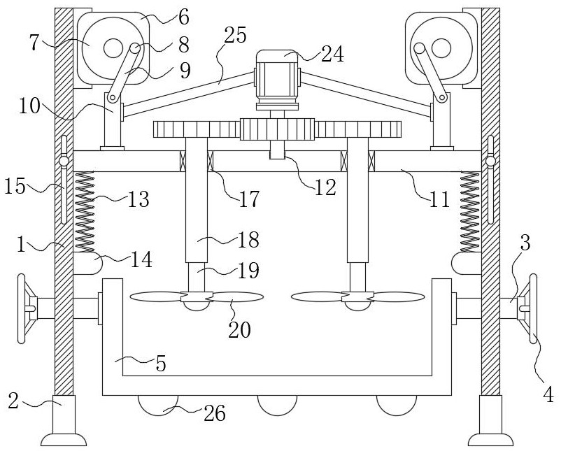
  • Construction waste crushing device capable of crushing large amount of construction waste
  • Construction waste crushing device capable of crushing large amount of construction waste
  • Construction waste crushing device capable of crushing large amount of construction waste

Examples


Embodiment Construction

[0028] The following will clearly and completely describe the technical solutions in the embodiments of the present invention with reference to the accompanying drawings in the embodiments of the present invention. Obviously, the described embodiments are only some, not all, embodiments of the present invention.

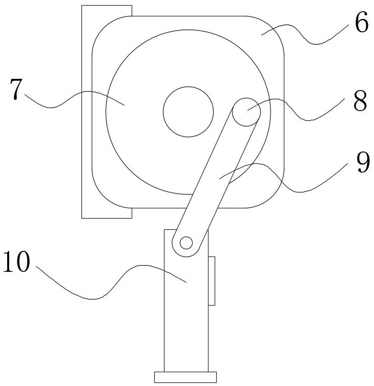
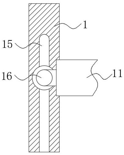
[0029] refer to Figure 1 to Figure 5 , a construction waste crushing device capable of crushing a large amount of construction waste, comprising a support frame 1, a base 2, a movable rod 3, a handle 4 and a storage box 5, the base 2 is fixedly connected to the lower end of the support frame 1, and the base The lower end of 2 is designed in the shape of a disc, which has a large contact area with the ground, thereby ensuring the stability of the support frame 1 during work. The movable rod 3 is inserted on the inner wall of the support frame 1, and the handle 4 is fixedly connected to the movable The left end of rod 3 and the right end of movable rod 3 run through s...


PUM


Abstract

The invention discloses a construction waste crushing device capable of crushing large amount of construction waste. The device comprises a supporting frame, bases, moving rods, rotating handles and astorage box, wherein the bases are fixedly connected to the lower end of the supporting frame, the moving rods are inserted into the inner wall of the supporting frame, the rotating handles are fixedly connected to the left ends of the moving rods, the right ends of the moving rods penetrate through the supporting frame and are fixedly connected to the side faces of the storage box, and first servo motors are fixedly connected to the upper side of the inner wall of the supporting frame. According to the device, during use, through cooperative use of structures such as the moving rods and balancing weights, the effect of simple and convenient discharging is achieved; through cooperative use of structures such as rotating discs and fixing seats, the effect of convenient lifting is achieved;through cooperative use of structures such as the rotating discs and the fixing seats, the effect of sufficient crushing is achieved; and through cooperative use of structures such as springs and sliding wheels, the effect of automatic returning is achieved.

Description

technical field [0001] The invention belongs to the technical field of construction waste, and in particular relates to a construction waste crushing device capable of crushing a large amount of construction waste. Background technique [0002] With the acceleration of the urbanization process and the continuous development of the economy, the city has accelerated the speed of metabolism, and a large number of old buildings have been demolished, which has produced a lot of construction waste. At the same time, some construction waste will also be generated when new buildings are built. The common solid wastes on the construction site of construction projects, some of which are larger, have been broken into multiple independent individuals during demolition. At present, the amount of construction waste in my country has accounted for nearly 40% of the total amount of urban waste. Calculated on the basis of 500-600 tons / 10,000 square meters, by 2020, my country will add about 3...

Claims


Application Information

Patent Timeline
IPC IPC(8): B02C13/20B02C13/18B02C13/26B02C13/286B02C13/30
CPCB02C13/18B02C13/20B02C13/26B02C13/286B02C13/30B02C2013/1857B02C2013/28609B02C2201/06
Inventor 张雷昌
Owner 张雷昌
Learn More