
Transmission structure of rotating mold

A technology of transmission structure and rotary mold, which is applied in the direction of perforating tools, manufacturing tools, forming tools, etc., can solve the problems of complex transmission structure, complex transmission mechanism, and easy failure of rotary molds, and reduce assembly difficulty and failure rate. Simple and reliable, the effect of reducing mechanical failure

Pending Publication Date: 2020-09-04
爱克(苏州)机械有限公司
View PDF0 Cites 0 Cited by
  • Summary
  • Abstract
  • Description
  • Claims
  • Application Information

AI Technical Summary

Problems solved by technology

[0002] The rotary mold is an important functional part of the CNC turret punching machine. The transmission structure of the rotary mold is relatively complicated, including a latch mechanism, a synchronous mechanism, and a locking mechanism. Mechanism, the servo motor drives the synchronous mechanism to rotate the angle according to the numerical control command. After the punching is completed, the servo motor returns to the origin, the latch mechanism exits, and the locking mechanism locks. This transmission mechanism is complex, prone to failure, and low in efficiency.

Method used


Image

  • Transmission structure of rotating mold
  • Transmission structure of rotating mold

Examples


Embodiment Construction

[0013] In order to make the purposes, technical solutions and advantages of the embodiments of the present invention clearer, the technical solutions in the embodiments of the present invention will be clearly and completely described below with reference to the accompanying drawings in the embodiments of the present invention. Obviously, the described embodiments These are some embodiments of the present invention, but not all of them. Based on the embodiments of the present invention, all other embodiments obtained by those of ordinary skill in the art without creative efforts shall fall within the protection scope of the present invention. Accordingly, the following detailed description of the embodiments of the invention provided in the accompanying drawings is not intended to limit the scope of the invention as claimed, but is merely representative of selected embodiments of the invention. Based on the embodiments of the present invention, all other embodiments obtained b...


PUM


Abstract

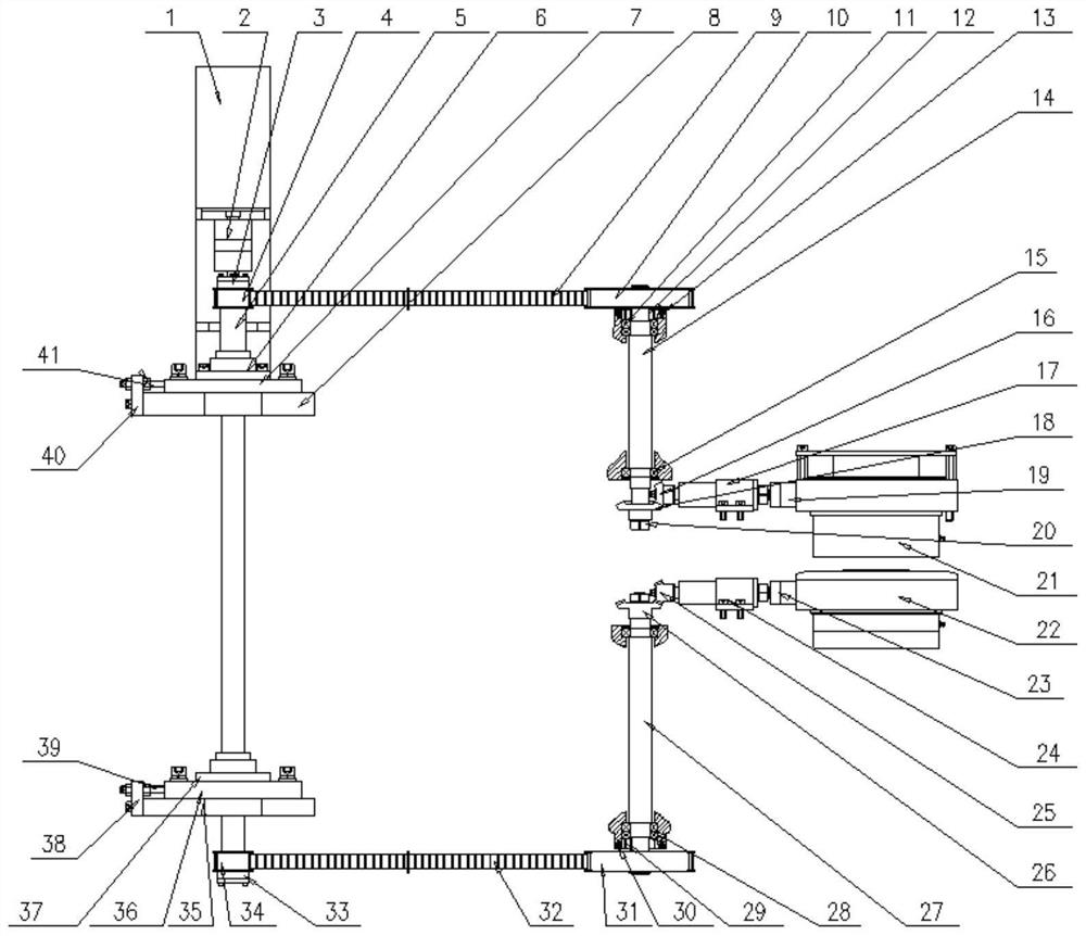
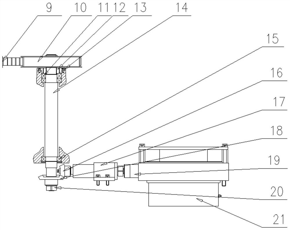
The invention discloses a transmission structure of a rotating mold. The transmission structure comprises a servo motor, a long transmission shaft coupling and a long transmission shaft. The servo motor drives the long transmission shaft through the long transmission shaft coupling. A first transmission mechanism and a second transmission mechanism are connected to the long transmission shaft. Thefirst transmission mechanism comprises a first tensioning sleeve, a first small synchronous belt wheel, a first large synchronous belt wheel and a first large bevel gear. The first small synchronousbelt wheel is fixed to the long transmission shaft through the first tensioning sleeve, the first large synchronous belt wheel is connected with the first small synchronous belt wheel through a firstsynchronous belt, the first large synchronous belt wheel is fixed to a first short transmission shaft, and the first large bevel gear is fixed to the first short transmission shaft. According to the transmission structure, the servo motor drives two rotating mold assemblies to achieve synchronous transmission through a transmission system, after punching is finished, the structure does not need toreturn to the zero point, action is simple and reliable, work efficiency is improved, a plug mechanism and a locking mechanism are omitted, and mechanical failures are reduced.

Description

technical field [0001] The invention relates to the related technical field of a numerical control turret punch press, in particular to a transmission structure of a rotary mold. Background technique [0002] The rotary mold is an important functional part of the CNC turret punching machine. The transmission structure of the rotary mold is relatively complicated, including a latch mechanism, a synchronous mechanism, and a locking mechanism. Mechanism, the servo motor drives the synchronous mechanism to rotate the angle according to the numerical control command. After the punching is completed, the servo motor returns to the origin, the latch mechanism exits, and the locking mechanism locks. This transmission mechanism is complex, prone to failure, and low in efficiency. Contents of the invention [0003] The purpose of the present invention is to provide a transmission structure of a rotary mold to solve the problems in the prior art. [0004] In order to achieve the abo...

Claims


Application Information

Patent Timeline
Patent Type & Authority Applications(China)
IPC IPC(8): B21D28/34B21D28/04B21D37/14
CPCB21D28/04B21D28/34B21D37/14
Inventor 吴凤江杨云沙晓慧
Owner 爱克(苏州)机械有限公司
Learn More