Unlock instant, AI-driven research and patent intelligence for your innovation.

Scanning galvanometer

A scanning galvanometer and lens technology, applied in the field of scanning galvanometers, can solve problems such as difficulty in further improvement, and achieve the effects of reducing the difficulty of debugging, reducing strength requirements, and improving scanning accuracy

Pending Publication Date: 2020-09-04
湖南中南智能激光科技有限公司
View PDF1 Cites 2 Cited by
  • Summary
  • Abstract
  • Description
  • Claims
  • Application Information

AI Technical Summary

Problems solved by technology

[0003] In the prior art, the precision and dynamic response time of the vibrating mirror motor largely determine the working performance of the entire vibrating mirror system. In the prior art, the X-axis vibrating mirror assembly and the Y-axis vibrating mirror assembly mostly use the motor to drive the lens to deflect. The technical scheme of laser deflection, such as the patent CN 107790892A discloses a kind of airtight scanning vibrating mirror device for laser machine, its X vibrating mirror mechanism includes X vibrating mirror motor, X vibrating mirror driven by X vibrating mirror motor, Y vibrating mirror The mirror mechanism includes the Y vibrating mirror motor and the Y vibrating mirror driven by the Y vibrating mirror motor, which adopts the above method, but the accuracy of the laser vibrating mirror in this scheme can only fluctuate at a limited level, and it is difficult to further improve

Method used


Image

  • Scanning galvanometer
  • Scanning galvanometer
  • Scanning galvanometer

Examples


Embodiment Construction

[0039] The present invention will be described in detail below in conjunction with the accompanying drawings. The description in this part is only exemplary and explanatory, and should not have any limiting effect on the protection scope of the present invention. In addition, those skilled in the art can make corresponding combinations of features in the embodiments in this document and in different embodiments according to the descriptions in this document.

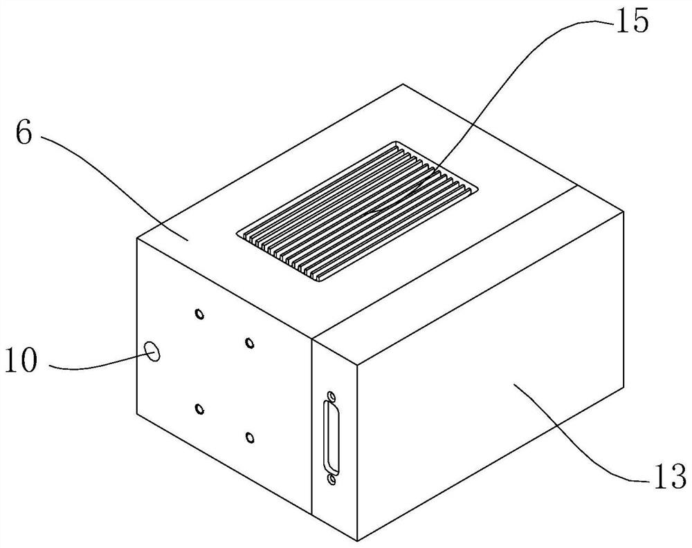
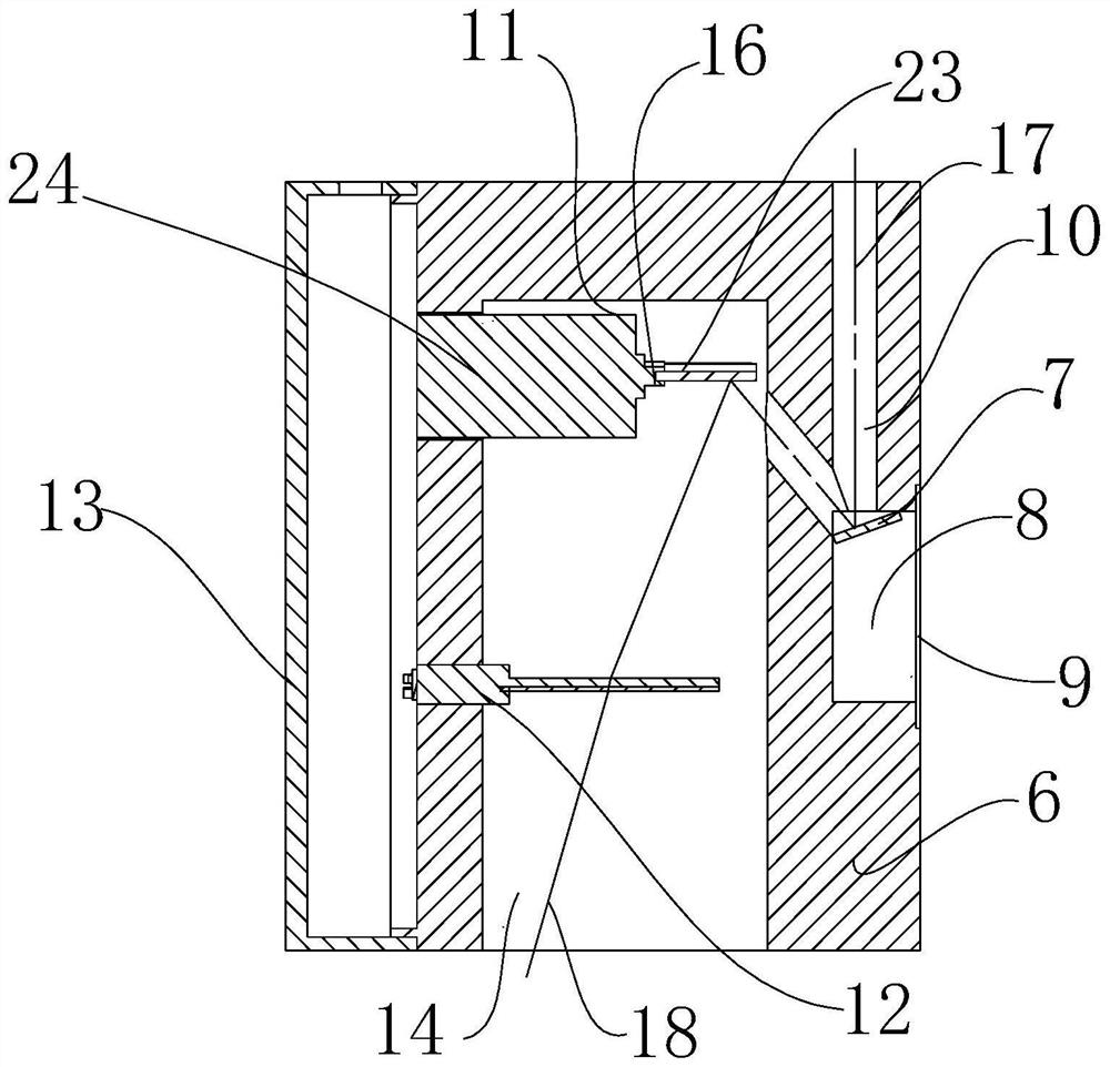
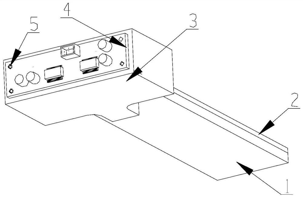
[0040] Embodiments of the present invention are as follows, with reference to Figure 1~4 , a scanning vibrating mirror, including a housing, an X-axis vibrating mirror assembly 11, a Y-axis vibrating mirror assembly 12 and a mirror 7, the housing is provided with a light inlet 10, a light outlet 14 and a mirror cavity 8, the The reflector 7 is arranged in the reflector cavity 8, the light entrance hole 10, the reflector cavity 8 and the light exit hole 14 are connected, and the X-axis vibrating mirror assembly 11 and th...


PUM


Abstract

The invention relates to a scanning galvanometer. The scanning galvanometer comprises a shell, an X-axis galvanometer assembly, a Y-axis galvanometer assembly and a reflector. The shell is provided with a light inlet hole, a light outlet hole and a reflector cavity. The light inlet hole, the reflector cavity and the light outlet hole communicate. The Y-axis galvanometer assembly comprises a variable refractive index lens assembly at a minimum. The variable refractive index lens assembly comprises a variable refractive index lens and a control module at a minimum. The control module is used forchanging an electric current of the variable refractive index lens or the magnetic field intensity of a magnetic field where the variable refractive index lens is located to further control the refractive index of the variable refractive index lens. Laser light enters the reflector through the light inlet hole to be reflected; and after the direction of the laser light is controlled to be deflected through the X-axis galvanometer assembly and the Y-axis galvanometer assembly in sequence, the laser light leaves the scanning galvanometer through the light outlet hole. According to the scanninggalvanometer, due to the fact that the Y-axis galvanometer assembly comprises the variable refractive index lens assembly at a minimum, the dynamic response speed is high; the scanning precision of the laser galvanometer can be improved; and in addition, the weight of a galvanometer device can be remarkably reduced, and the strength requirement for a galvanometer fixing support is lowered.

Description

technical field [0001] The invention belongs to the field of micro-electromechanical technology, and in particular relates to a scanning vibrating mirror. Background technique [0002] The laser galvanometer is an optical scanner composed of a driver board and a high-precision oscillating motor. It is widely used in laser marking, laser welding, laser cutting, laser 3D printing, and laser detection and projection. When the existing laser galvanometer is in operation, the laser emits laser light, which shines on the total reflection lens of the galvanometer, and the beam is deflected on the lens through the swing of the galvanometer motor, and the scanning process of the specified position within a certain range is completed. [0003] In the prior art, the precision and dynamic response time of the vibrating mirror motor largely determine the working performance of the entire vibrating mirror system. In the prior art, the X-axis vibrating mirror assembly and the Y-axis vibrat...

Claims


Application Information

Patent Timeline
IPC IPC(8): B23K26/064B23K26/082B23K26/70
CPCB23K26/064B23K26/082B23K26/702
Inventor 蒋韬吴葛铭徐岩易江肖高雄王建忠
Owner 湖南中南智能激光科技有限公司
Features
  • R&D
  • Intellectual Property
  • Life Sciences
  • Materials
  • Tech Scout
  • Unparalleled Data Quality
  • Higher Quality Content
  • 60% Fewer Hallucinations
Learn More