Robot joint closed-loop braking device

A technology of robot joints and braking devices, which is applied in the direction of manipulators, manufacturing tools, joints, etc., can solve the problems of heavy load of the robot itself, poor reliability of the braking mechanism, increased power consumption, etc., and achieve a compact overall structure layout, easy assembly, The effect of reducing gravity

Pending Publication Date: 2020-09-04
徐静
View PDF1 Cites 0 Cited by
  • Summary
  • Abstract
  • Description
  • Claims
  • Application Information

AI Technical Summary

Problems solved by technology

[0002] As we all know, with the rapid development of robot technology and the acceleration of social industrialization, robots are gradually participating in human production activities; articulated manipulators are also an important type of robots, and articulated manipulators are used in assembly, spraying, Cutting and other engineering technology fields play an irreplaceable important role; when the robot performs the operation task, the positioning of the mechanical claw at the end of the robot is realized through the joint action of multiple robot joints, so the mechanical arm joints are in operation. It is often necessary to brake to achieve a certain action, but most of the robot joint brake systems currently use electromagnetic brakes, and the electromagnetic brake system is bulky, resulting in a large load on the robot itself, and the existing electromagnetic brakes are generally brake input terminals. Electromagnetic force needs to be used in the state, the heating phenomenon is serious, and the reliability is poor. In order to ensure the smooth operation of the mechanical arm, the motor needs to provide the reverse force, which greatly increases the consumption of electric energy. This phenomenon is urgently needed by those skilled in the art. The problem;
[0003] Chinese patent (notification number: CN210704822U) discloses a brake mechanism, a joint driver and a robot. A brake mechanism for motors in this patent includes friction parts, brake parts, thrust parts and a locking mechanism; when braking is required, The locking mechanism cooperates with the brake member to prevent the brake member from rotating, and the friction member and the rotor of the motor also gradually stop moving under the action of friction; but the brake mechanism of this patent is less reliable, and high power consumption

Method used


Image

  • Robot joint closed-loop braking device
  • Robot joint closed-loop braking device
  • Robot joint closed-loop braking device

Examples


Embodiment 1

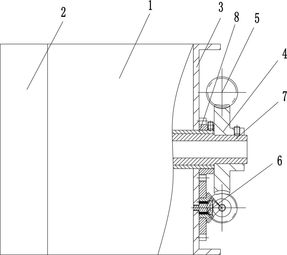
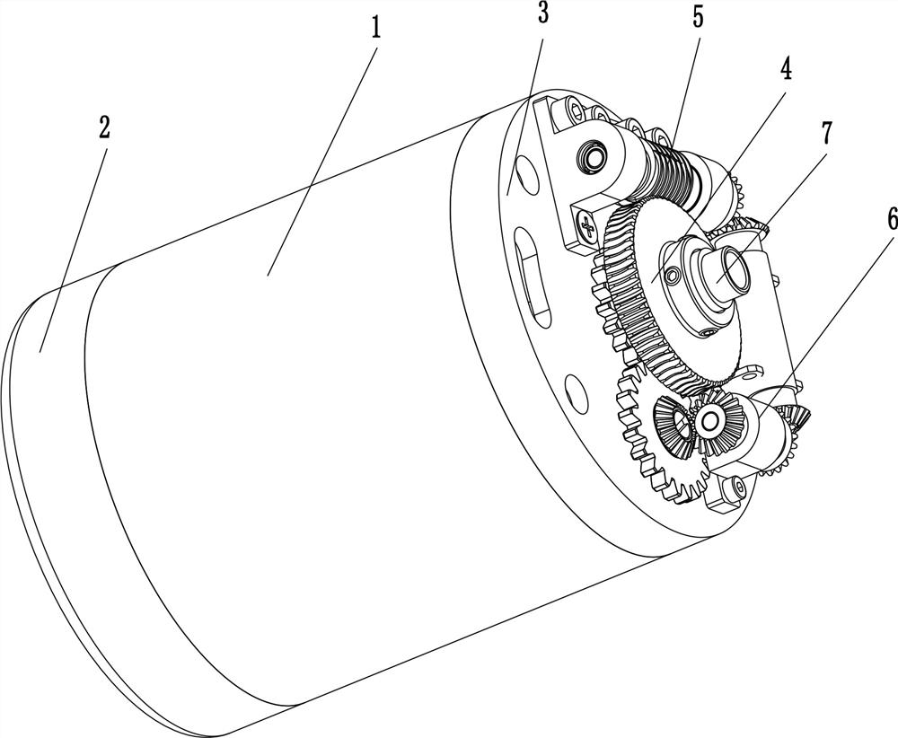
[0029] Embodiment one: see attached Figure 1~3 ;

[0030]The power transmission device 6 includes a gear 6-1, an intermediate wheel I 6-2, a bridge shaft I 6-3 and an electromagnetic clutch 6-4. The motor shaft 8 is provided with a gear 6-1, and the gear 6- 1 is connected to one end of the bridge shaft I6-3 through the corresponding transmission of the intermediate wheel I6-2. The 3-axis body is equipped with an electromagnetic clutch 6-4, and the other end of the bridge shaft I 6-3 is connected to the worm 5 in a corresponding transmission, that is, during normal operation, the electromagnetic clutch 6-4 is closed, so that the motor shaft 8 can drive the gear 6- 1 Drive the intermediate wheel I6-2, the intermediate wheel I6-2 drives the bridge shaft I6-3, and the bridge shaft I6-3 drives the worm 5, so that the worm 5 and the worm wheel 4 run synchronously, thus forming a closed-loop transmission structure; When braking is required, the motor body 1 is disconnected from th...

Embodiment 2

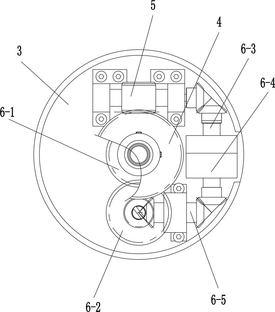
[0031] Embodiment two: see attached figure 1 , 2 and 4;

[0032] The power transmission device 6 includes a pin wheel 6-6, an intermediate wheel II 6-7 and a bridge shaft II 6-8, and the motor shaft 8 is provided with a pin wheel 6-6, and the pin wheel 6-6 is connected to the bridge shaft II 6-8. One end of the bridge shaft Ⅱ6-8 is connected through the corresponding transmission of the intermediate wheel Ⅱ6-7, and the tooth groove width of the pin wheel 6-6 is greater than the tooth thickness of the intermediate wheel Ⅱ6-7, and the intermediate wheel Ⅱ6-7 and the bridge shaft Ⅱ6-8 are both Corresponding to the mounting seat 3, the other end of the bridge shaft II 6-8 is connected to the worm 5 in a corresponding transmission connection, that is, in normal operation, the motor shaft 8 can drive the pin wheel 6-6 to drive the intermediate wheel II 6-7. Wheel Ⅱ6-7 drives the bridge shaft Ⅱ6-8, and the bridge shaft Ⅱ6-8 drives the worm 5, so that the worm 5 and the worm gear 4 ...

Embodiment 3

[0033] Embodiment three: see attached figure 1 , 2 and 5;

[0034] The power transmission device 6 includes an intermediate wheel III 6-10, a bridge shaft III 6-11 and an elastic gear 6-12 whose gear teeth are made of elastomer plastic, and the motor shaft 8 is provided with an elastic gear 6-12, One end of the elastic gear 6-12 and the bridge shaft III 6-11 is connected through the corresponding transmission of the intermediate wheel III 6-10, and the intermediate wheel III 6-10 and the bridge shaft III 6-11 are connected to the mounting seat 3 in rotation correspondingly, so The other end of bridge shaft III 6-11 is correspondingly connected with worm 5, that is, in normal operation, motor shaft 8 can drive elastic gear 6-12 to drive intermediate wheel III 6-10, and intermediate gear III 6-10 drives bridge shaft III 6 -11, the bridge shaft III6-11 drives the worm 5, so that the worm 5 and the worm gear 4 run synchronously, thus forming a closed-loop transmission structure;...


PUM


Abstract

The invention discloses a robot joint closed-loop braking device, and relates to the technical field of robot joint brake. A motor body and a coaxial speed reducer body are included. An installing base, a worm gear, a worm and a power transmission device are further included. The motor body and the coaxial speed reducer body are correspondingly in transmission connection. An output shaft of the coaxial speed reducer body is in transmission connection with the worm gear. The installing base is correspondingly in fastened connection with one end of a motor body machine shell. The installing baseis rotationally connected with the worm which is correspondingly in meshing transmission with the worm gear. The cooperation deceleration ratio of the worm gear and the worm is correspondingly consistent to the deceleration ratio of the coaxial speed reducer body. One end of the worm is correspondingly in transmission connection with a motor shaft of the motor body through a power transmission device capable of being disconnected. The transmission ratio of the motor shaft of the motor body, the power transmission device and the worm is 1:1. The robot joint closed-loop braking device effectively solves the problems that an existing braking system is poor in reliability, high in energy consumption and large in size.

Description

technical field [0001] The invention relates to the technical field of robot joint brakes, in particular to a closed-loop brake device for robot joints. Background technique [0002] As we all know, with the rapid development of robot technology and the acceleration of social industrialization, robots are gradually participating in human production activities; articulated manipulators are also an important type of robots, and articulated manipulators are used in assembly, spraying, Cutting and other engineering technology fields play an irreplaceable important role; when the robot performs the operation task, the positioning of the mechanical claw at the end of the robot is realized through the joint action of multiple robot joints, so the mechanical arm joints are in operation. It is often necessary to brake to achieve a certain action, but most of the robot joint brake systems currently use electromagnetic brakes, and the electromagnetic brake system is bulky, resulting in...

Claims


Application Information

Patent Timeline
Patent Type & Authority Applications(China)
IPC IPC(8): B25J17/00B25J17/02B25J19/00
CPCB25J17/00B25J17/02B25J19/00B25J19/0004
Inventor 石东海王晓峰
Owner 徐静
Why Eureka
Try Eureka