Voltage-controlled resistor circuit

A technology of voltage-controlled resistors and resistors, applied in the direction of adjusting electrical variables, control/regulation systems, instruments, etc., can solve the problems of inability to continuously change the adjustable range of resistance, adjustable resistance mechanical structure resistance, etc., to achieve simple structure, The resistance value can be changed continuously and the resistance value can be adjusted in a large range

Pending Publication Date: 2020-09-04
CHENGDU NORMAL UNIV
View PDF0 Cites 2 Cited by
  • Summary
  • Abstract
  • Description
  • Claims
  • Application Information

AI Technical Summary

Problems solved by technology

[0005] The technical problem to be solved by the present invention is to provide a voltage-controlled resistance circuit to solve the problems that the existing adjustable resistance has a mechanical structure or the resistance value cannot be continuously changed or the resistance value adjustable range is narrow

Method used


Image

  • Voltage-controlled resistor circuit
  • Voltage-controlled resistor circuit
  • Voltage-controlled resistor circuit

Examples


Embodiment Construction

[0013] The principles and features of the present invention are described below in conjunction with the accompanying drawings, and the examples given are only used to explain the present invention, and are not intended to limit the scope of the present invention.

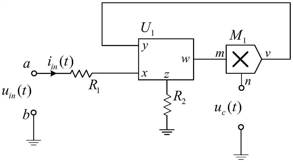
[0014] like figure 1 As shown, the voltage-controlled resistor circuit, including the resistor R 1 , resistance R 2 , current transmitter U 1 and multiplier M 1 ; resistance R 1 One end is connected to the input port a, the resistance R 1 The other end of the current transmitter U 1 The x pin is connected to the current conveyor U 1 the z pin with resistor R 2 Connected to one end of the resistor R 2 The other end of the ground, the current transmitter U 1 The w pin is connected with the multiplier M 1 The input terminal m pin is connected to the current conveyor U 1 The y pin is connected with the multiplier M 1 The output terminal v is connected to the multiplier M 1 The input terminal n pin and the c...


PUM


Abstract

The invention discloses a voltage-controlled resistor circuit which comprises a resistor R1, a resistor R2, a current transmitter U1 and a multiplier M1. The invention aims to solve the problem that the existing adjustable resistor contains a mechanical structure or the resistance value cannot be continuously changed or the adjustable range of the resistance value is narrow. The electrical characteristics of the ports a and b are equivalent to the resistance characteristics, the change of the resistance value is controlled by the voltage uc(t), only four components need to be used, and the device has the advantages of being simple in structure, convenient to implement, free of mechanical parts, capable of continuously changing the resistance value and large in resistance value adjusting range. The voltage-controlled resistor circuit can be widely applied to various circuit design occasions needing the adjustable resistor (especially a voltage-controlled resistor).

Description

technical field [0001] The patent of the present invention relates to the field of adjustable resistance circuit design, in particular to a voltage-controlled resistance circuit. Background technique [0002] In circuit design, it is sometimes necessary to use adjustable resistors. Adjustable resistors mainly include potentiometers, resistor boxes, sensitive resistors, digital potentiometers, adjustable resistor circuits, etc. [0003] A potentiometer is a mechanical component that converts a change in mechanical displacement into a change in resistance value. It is generally composed of a resistive entity and a movable brush. Generally, the potentiometer can only change the resistance value continuously qualitatively, and it is difficult to know the specific value to which the resistance value has been adjusted. The resistance box can change the resistance value by turning different knobs, and the adjustment dial indicates the resistance value. The resistance value of th...

Claims


Application Information

Patent Timeline
Patent Type & Authority Applications(China)
IPC IPC(8): G05F1/56
CPCG05F1/561
Inventor 余波
Owner CHENGDU NORMAL UNIV
Why Eureka
Try Eureka