Design of a water level measurement system for a pressure stabilizer to cope with rapid pressure relief conditions
A technology for water level measurement and system design, which is applied to display liquid level indicators through pressure measurement, reactors, nuclear engineering, etc. It can solve problems such as poor measurement accuracy, inability to isolate containers and capillaries to obtain a continuous and stable reference water level, etc. The effect of simplicity and convenience, reducing errors, and reducing the difficulty of installation and maintenance
- Summary
- Abstract
- Description
- Claims
- Application Information
AI Technical Summary
Problems solved by technology
Method used
Image
Examples
Embodiment 1
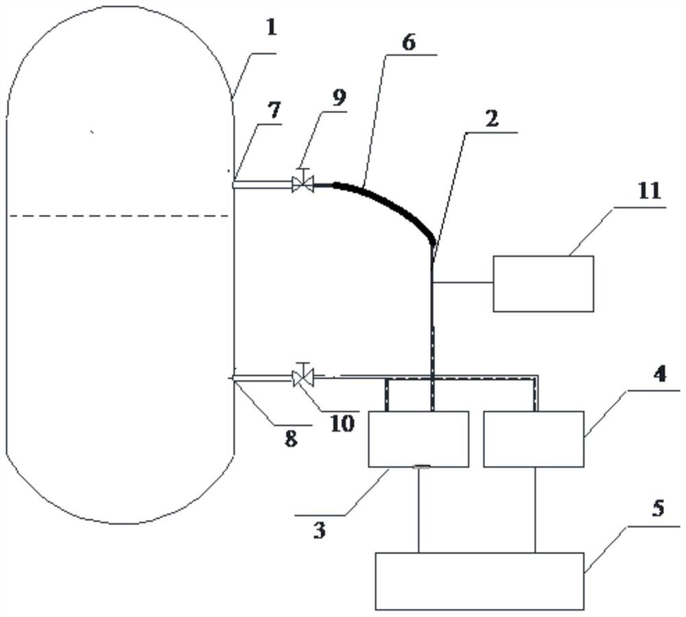
[0027] like figure 1 As shown in the figure, a design of a water level measurement system for a pressurizer to deal with a rapid pressure relief condition, including several redundant measurement channels for measuring the water level of the pressurizer 1, and the redundant measurement channels include a water level measurement channel for steam condensation, It also includes a pressure transmitter 4 and a temperature measuring instrument 11, the pressure transmitter 4 is used to measure the pressure of the voltage stabilizer, and the temperature measuring instrument 11 is used to measure the condensed water after the condensed metal hose 6 condenses the steam. temperature.
[0028] In this embodiment, the condensing metal hose 6 is a 1 / 2 OD" condensing metal hose, and the condensing metal hose 6 forms a condensing ring. The condensing ring can play a similar role as a condensing container, and can also play the role of an expansion ring; In addition, the condensing metal hos...
Embodiment 2
[0030] like figure 1 As shown, this embodiment is further limited on the basis of Embodiment 1, and also includes the upper pressure-taking joint 7, the lower pressure-taking joint 8, and the pressure-inducing pipe 2 arranged on the voltage stabilizer 1. The condensation metal The two ends of the hose 6 are respectively connected with the upper pressure-taking joint 7 and one end of the pressure-inducing pipe 2, and the end of the condensing metal hose 6 connected with the pressure-inducing pipe 2 is the outlet end, and the other end of the pressure-inducing pipe 2 is connected to the outlet. The lower pressure-taking joint 8 is communicated through a pipeline.
[0031] It also includes an upper root valve 9 and a lower root valve 10 for controlling the opening and closing of the upper pressure-taking joint 7 and the lower pressure-taking joint 8 respectively.
[0032] Further, the pressure transmitter 4 is arranged near the interface of the pressure-inducing pipe 2 and the c...
Embodiment 3
[0039] like figure 1 As shown, each measurement channel includes a pressure transmitter 4 , a differential pressure transmitter 3 , a temperature measurement instrument 11 and a secondary measurement signal processing device 5 . The high pressure side of the differential pressure transmitter 3 is connected to the lower root valve 10, and the low pressure side of the differential pressure transmitter 3 is connected to a section of 1 / 2OD" condensing metal hose 6 behind the pressure pipe 2 of the upper root valve 9, and forms a condensation ring .
[0040] The secondary measurement signal processing device 5 receives the signals from the pressure transmitter 4, the differential pressure transmitter 3 and the temperature measuring instrument 11 to calculate the water level.
[0041] The calculation process of the water level measurement of the voltage stabilizer:
[0042] First of all, under cold working conditions (about 25°C, for example: 25°, 23°, 26°, etc.), after the instru...
PUM
 Abstract
Description
Claims
Application Information
 - R&D
- Intellectual Property
- Life Sciences
- Materials
- Tech Scout
- Unparalleled Data Quality
- Higher Quality Content
- 60% Fewer Hallucinations
Browse by: Latest US Patents, China's latest patents, Technical Efficacy Thesaurus, Application Domain, Technology Topic, Popular Technical Reports.
© 2025 PatSnap. All rights reserved.Legal|Privacy policy|Modern Slavery Act Transparency Statement|Sitemap|About US| Contact US: help@patsnap.com


