Outer-layer variable heat dissipation structure of transformer

A heat dissipation structure and transformer technology, applied in the field of transformer equipment, can solve the problems of limited heat dissipation effect, decomposition of transformer oil, and inability to dissipate heat to the outside in time, and achieve the effect of improving heat dissipation effect.

Active Publication Date: 2020-09-04
河南龙键电力装备有限公司
View PDF5 Cites 17 Cited by
  • Summary
  • Abstract
  • Description
  • Claims
  • Application Information

AI Technical Summary

Problems solved by technology

For small-capacity transformers, smooth oil tank surface is enough to cool the oil; for medium-capacity transformers, the surface of the oil tank should be wrinkled to increase the heat dissipation surface, or a fin or flat tube radiator should be installed to make the oil circulate in the radiator A radiation radiator should be added on the surface of the large-capacity transformer oil tank, but the existing transformer oil tank is basically static and passive during heat dissipation, and the heat dissipation effect is very limited, resulting in that the heat cannot be dissipated to the outside in time, resulting in local overheating inside the oil tank, and then Cause the transformer oil to decompose and produce gas, which affects the normal use of the transformer

Method used


Image

  • Outer-layer variable heat dissipation structure of transformer
  • Outer-layer variable heat dissipation structure of transformer
  • Outer-layer variable heat dissipation structure of transformer

Examples


Embodiment 1

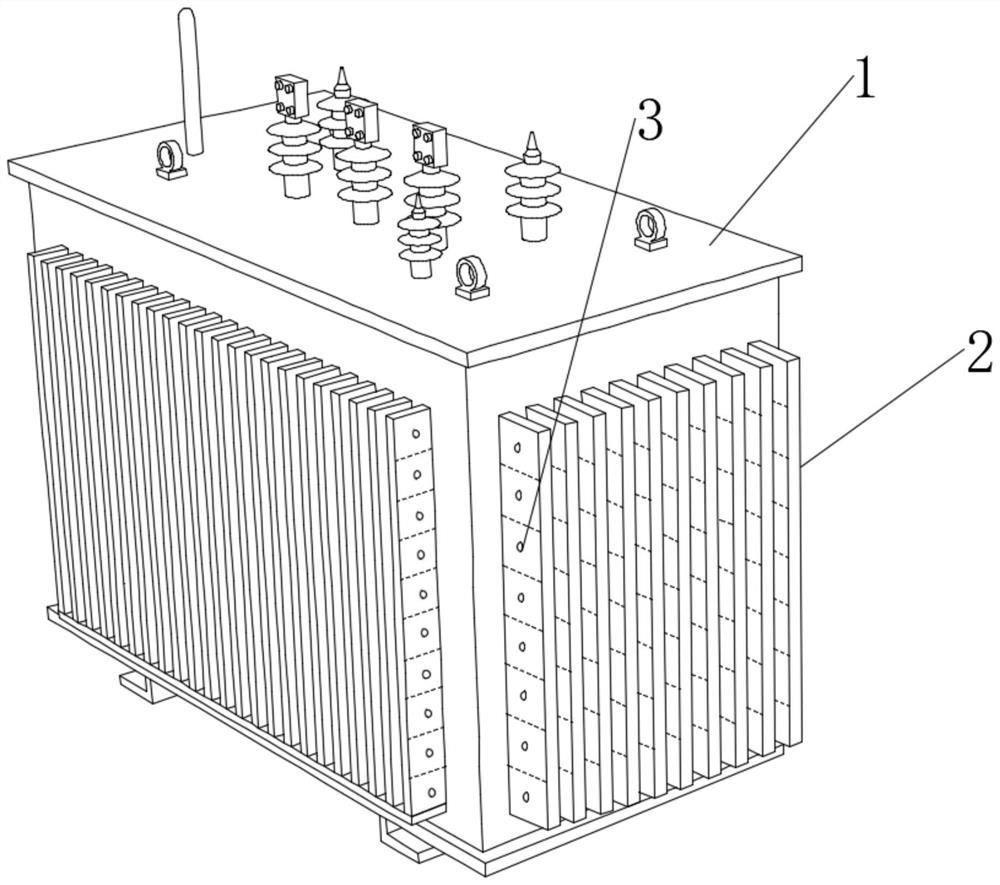
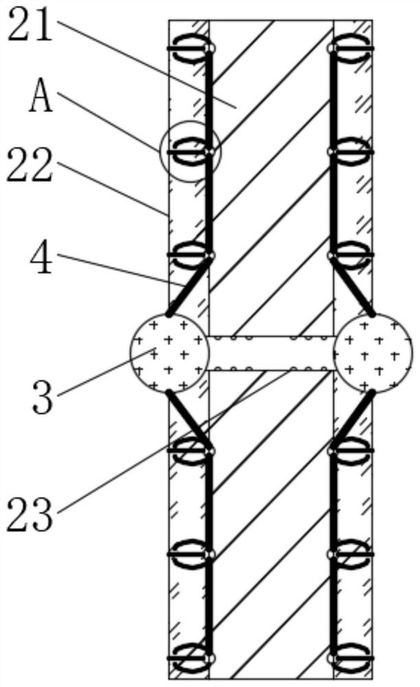
[0043] see Figure 1-2 , a variable heat dissipation structure for the outer layer of a transformer, including a transformer body 1, a plurality of evenly distributed variable heat sinks 2 connected to the outer end of the transformer body 1, the variable heat sink 2 includes a plurality of variable heat dissipation units, and the variable heat dissipation The unit includes a heat dissipation substrate 21 and two shape transformation heat layers 22, the shape transformation heat layer 22 is covered on the two side walls of the heat dissipation substrate 21, and the heat dissipation substrate 21 is connected with the transformer body 1, and the center of the shape transformation heat layer 22 A water-based ball 3 is inlaid and connected, and a thermal extension trigger cylinder 23 is inlaid and connected to the center of the heat dissipation substrate 21, and both ends of the thermal extension trigger cylinder 23 are respectively connected with the water-based balls 3 on both si...


PUM

PropertyMeasurementUnit
thicknessaaaaaaaaaa

Abstract

The invention discloses an outer-layer variable heat dissipation structure of a transformer, and belongs to the technical field of transformer equipment. Composite variable cooling fins can be innovatively introduced into the transformer body. The deformable shape-change heat exchange layer is attached to the heat dissipation substrate for rapid heat conduction. An external water-absorbing water-based ball is used as a cold source. A thermal extension trigger cylinder arranged in the heat dissipation substrate generates an expansion phenomenon after sensing heat. On one hand, the water-based balls are extruded to release water, and on the other hand, the expansion action of the thermal extension trigger cylinder is continued, the water-based ball is also used for pulling the shape-change heat exchange layer to deform to form a shape similar to a tent, and performing second cooperation with the thermal extension trigger cylinder. The outer surface of the heat dissipation substrate can be exposed, water can absorb heat conveniently to achieve evaporation, meanwhile, the shape change heat exchange layer wraps the heat extension trigger cylinder and then absorbs heat away, the heat extension trigger cylinder restores to conduct the next time of variable heat dissipation, and therefore the heat dissipation effect of the transformer is remarkably improved.

Description

technical field [0001] The invention relates to the technical field of transformer equipment, and more specifically, relates to a transformer outer layer variable heat dissipation structure. Background technique [0002] A transformer is a static electrical device used to convert AC voltage and current to transmit AC power. It is based on the principle of electromagnetic induction to achieve electrical energy transfer. Transformers can be divided into power transformers, test transformers, instrument transformers and special-purpose transformers in terms of their uses: power transformers are necessary equipment for power transmission and distribution, and power distribution for power users; test transformers can withstand voltage (boost) for electrical equipment Test equipment; instrument transformers are used for electrical measurement and relay protection of power distribution systems (PT, CT); special-purpose transformers include electric furnace transformers for smeltin...

Claims


Application Information

Patent Timeline
Patent Type & Authority Applications(China)
IPC IPC(8): H01F27/22H01F27/16H01F27/18H01F27/20
CPCH01F27/16H01F27/18H01F27/20H01F27/22
Inventor 杨成
Owner 河南龙键电力装备有限公司
Why Eureka
Try Eureka