Method, device and circuit for determining energy storage capacitor in electronic detonator

An energy storage capacitor and electronic detonator technology, which is applied to battery circuit devices, circuit devices, systems for storing electrical energy, etc., can solve the problems of low accuracy and large error in the calculation result of the capacity value of the energy storage capacitor, and achieves improved accuracy. sexual effect

Active Publication Date: 2020-09-04
BEIJING QAML OF SCI & TECH CO LTD
View PDF9 Cites 2 Cited by
  • Summary
  • Abstract
  • Description
  • Claims
  • Application Information

AI Technical Summary

Problems solved by technology

[0002] The electronic detonator is the product of the combination of detonator and integrated circuit technology. It has been widely used at present. The electronic detonator control module generally has a large-capacity energy storage capacitor. The determination of the capacitance value of the energy storage capacitor is very important for detonation. In order to determine the capacity value of the energy storage capacitor, the charging current calculation method is mainly used in the prior art: charge the energy storage capacitor to a predetermined voltage value, measure the charging current during the charging process and the time required to reach the predetermined voltage, and then charge The current calculates the capacity of the energy storage capacitor; the charging current flow of the electronic detonator is small, about 2mA, and it changes with the change of the capacitor voltage, causing the host to have low accuracy in sampling the current; eventually it will cause the energy storage capacitor The calculation result of the capacity value has a large error

Method used


Image

  • Method, device and circuit for determining energy storage capacitor in electronic detonator
  • Method, device and circuit for determining energy storage capacitor in electronic detonator
  • Method, device and circuit for determining energy storage capacitor in electronic detonator

Examples


Embodiment Construction

[0055] The implementation mode of the present invention is illustrated by specific specific examples below, and those who are familiar with this technology can easily understand other advantages and effects of the present invention from the contents disclosed in this description. Obviously, the described embodiments are a part of the present invention. , but not all examples. Based on the embodiments of the present invention, all other embodiments obtained by persons of ordinary skill in the art without making creative efforts belong to the protection scope of the present invention.

[0056] Electronic detonator: also known as digital electronic detonator, digital detonator or industrial digital electronic detonator, that is, an electric detonator that uses an electronic control module to control the detonation process. It generally includes two parts, the electronic detonator and the electronic chip, see the attached figure 1 The schematic diagram of the electronic detonator...


PUM


Abstract

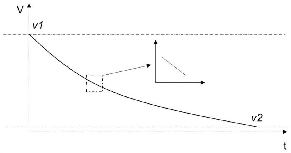
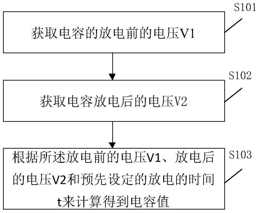
The embodiment of the invention relates to the technical field of electronic detonators, in particular to a method, device and circuit for determining an energy storage capacitor in an electronic detonator. The method comprises the steps: enabling the relation between capacitor charging and time to be approximate to a bit linear relation through the micro-conduction time; designing a high-precision clock, so that a host can accurately set the capacitor discharge time t; obtaining the voltage V1 of the capacitor before discharging by using a high-precision digital-to-analog converter; obtaininga voltage V2 after the capacitor is discharged after the capacitor is discharged; and calculating an RC value according to the voltage V1 before discharging, the voltage V2 after discharging and a preset discharging time t. During a specific test, a standard resistor similar to an internal resistor of an ignition head is selected, and a high-precision capacitance value can be simply and conveniently obtained. According to the invention, the capacitance value is calculated by accurately controlling the capacitance time and directly measuring the voltage, and the accuracy of capacitance calculation is improved.

Description

technical field [0001] Embodiments of the present invention relate to the technical field of electronic detonators, in particular to a method, device and circuit for determining an energy storage capacitor in an electronic detonator. Background technique [0002] The electronic detonator is the product of the combination of detonator and integrated circuit technology. It has been widely used at present. The electronic detonator control module generally has a large-capacity energy storage capacitor. The determination of the capacitance value of the energy storage capacitor is very important for detonation. In order to determine the capacity value of the energy storage capacitor, the charging current calculation method is mainly used in the prior art: charge the energy storage capacitor to a predetermined voltage value, measure the charging current during the charging process and the time required to reach the predetermined voltage, and then charge The current calculates the c...

Claims


Application Information

Patent Timeline
Patent Type & Authority Applications(China)
IPC IPC(8): H02J15/00H02J7/34
CPCH02J15/00H02J7/345
Inventor 黄圣专关硕王昭
Owner BEIJING QAML OF SCI & TECH CO LTD
Why Eureka
Try Eureka