Brushless disc double rotor motor

A dual-rotor motor and brushless disc technology, applied in motors, electric components, electric vehicles, etc., can solve the problems of inconvenient maintenance and replacement of intermediate phase windings, inconvenient manufacture or maintenance of outer rotor windings, low efficiency and reliability, etc. , to achieve the effect of light weight, compact structure and compact internal structure

Active Publication Date: 2022-05-17
陕西榆林能源集团横山煤电有限公司
View PDF7 Cites 0 Cited by
  • Summary
  • Abstract
  • Description
  • Claims
  • Application Information

AI Technical Summary

Problems solved by technology

Since the motor has only one rotor, it can only achieve single-speed single-axis output
In applications such as torpedo propulsion, electric vehicles, and wind power generation, the motor is required to have a dual-axis output capability that provides two independent speeds, which cannot be achieved by traditional motors
[0003] In the existing dual-rotor motors, such as the dual-rotor hybrid compound permanent magnet motor disclosed in the application number 200510014393.2, there are brushes and slip rings, resulting in low efficiency and reliability
For example, the brushless dual-rotor motor disclosed in the application number 200610014350.9 realizes brushless and improves reliability. Because it adopts double-feed technology, the outer rotor is composed of windings, resulting in large copper loss. Manufacture or repair of outer rotor windings It is also very inconvenient, and its overall weight and volume are relatively large
Such as the application number is 200910179233.1 disclosed brushless feed double rotor motor has been improved and improved in terms of efficiency, maintenance, reliability, but because its three-phase stator winding, claw pole outer rotor, magnetic steel inner rotor are independent, so The utilization rate of the inner and outer rotors and the magnetic steel is only 2 / 3. In addition, the winding is inconvenient to embed, making it difficult to mass produce, and it is also inconvenient to repair and replace the intermediate phase winding.

Method used


Image

  • Brushless disc double rotor motor
  • Brushless disc double rotor motor
  • Brushless disc double rotor motor

Examples


Embodiment

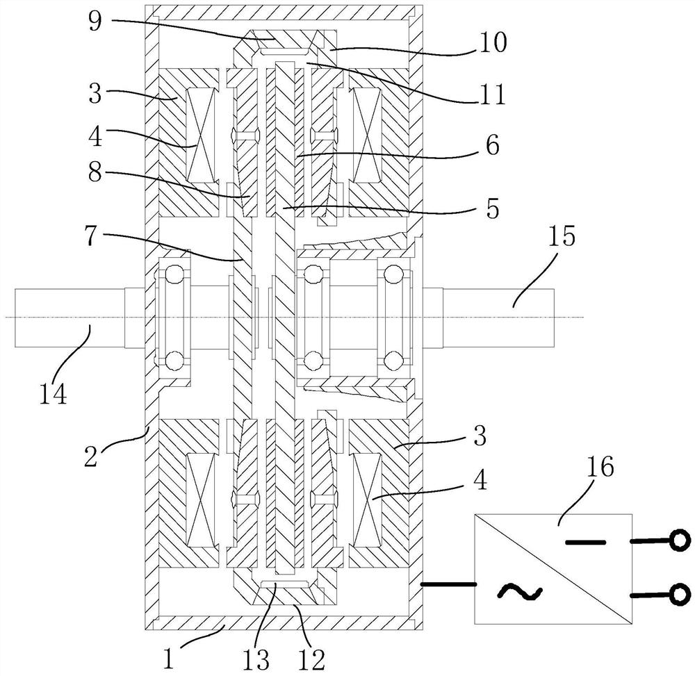
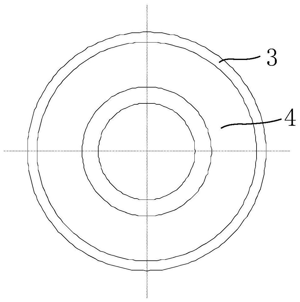
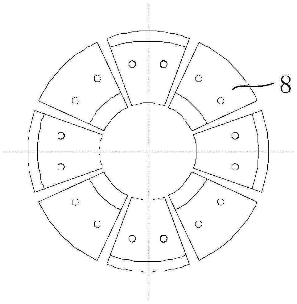
[0034] Such as Figure 1 to Figure 4 As shown, the brushless disc-type double-rotor motor includes motor housing, stator, inner rotor, inner rotor output shaft 15, outer rotor, outer rotor output shaft 14, inverter 16 and other components, wherein the inverter is preferably Two-phase inverter, the specific structure of each component is as follows:

[0035] The motor casing is mainly used to accommodate and protect various components, specifically including the casing 1 and the end cover 2 . Among them, the shell is cylindrical, and the two end caps are respectively fixed at its two ends to form a space for accommodating various components, and maintain a certain gap with the internal components. There is a through hole in the center of the end cap, and the through hole Equipped with one-piece shaft sleeve, the output shaft of the inner rotor and the output shaft of the outer rotor are respectively placed in the through holes of the two end covers and the shaft sleeve through...


PUM


Abstract

The invention discloses a brushless disc type double-rotor motor, which comprises a motor housing, a stator fixedly arranged inside the axial ends of the motor housing, an outer rotor arranged in the motor housing and matched with the stator, and One end of the motor housing is rotatably connected to the outer rotor output shaft fixedly connected to the outer rotor, and the inner rotor arranged in the motor housing and matched with both the stator and the outer rotor is rotatably connected to the other end of the motor housing and connected to the inner rotor. The output shaft of the inner rotor is fixedly connected, and the inverter is electrically connected to the stator. The present invention has the characteristics of a disc-type permanent magnet motor, the stator is fixed on the inner side of the end covers at both ends, the permanent magnet inner rotor is fixed on the inner rotor output shaft to rotate together, the claw pole rotor is located between the two-phase stator and the inner rotor, and They form an electrical angle of 90° to each other, and are fixed on the output shaft of the outer rotor to rotate together. Only a set of two-phase inverters can be used to coordinate the work to realize brushless power feeding and the speed / torque difference between the two shafts. adjust.

Description

technical field [0001] The invention relates to a double-rotor motor, in particular to a brushless disc-type double-rotor motor. Background technique [0002] Traditional motors generally consist of a stator and a rotor. Since the motor has only one rotor, it can only achieve single-speed single-axis output. In applications such as torpedo propulsion, electric vehicles, and wind power generation, the motor is required to have dual-axis output capabilities that provide two independent speeds, which cannot be achieved by traditional motors. [0003] In the existing dual-rotor motors, such as the dual-rotor hybrid compound permanent magnet motor disclosed in the application number 200510014393.2, there are brushes and slip rings, resulting in low efficiency and reliability. For example, the brushless dual-rotor motor disclosed in the application number 200610014350.9 realizes brushless and improves reliability. Because it adopts double-feed technology, the outer rotor is comp...

Claims


Application Information

Patent Timeline
Patent Type & Authority Patents(China)
IPC IPC(8): H02K16/02H02K1/12H02K1/16H02K1/22H02K1/24H02K1/2796H02K1/2706H02K1/274H02K1/32H02K9/06
CPCH02K16/02H02K1/12H02K1/165H02K1/22H02K1/243H02K1/2793H02K1/2706H02K1/32H02K9/06Y02T10/64
Inventor 高利孝
Owner 陕西榆林能源集团横山煤电有限公司
Why Eureka
Try Eureka