
Photonic IoT Lighting Base Station

A technology of the Internet of Things and photonics, applied in the field of the Internet of Things, can solve problems affecting health, electromagnetic interference, and high power consumption, and achieve the effect of realizing high-speed and safe Internet of Things construction, avoiding impacts, and reducing capacity constraints

Active Publication Date: 2021-10-08
OTN INTELLIGENT TECH (SUZHOU) CO LTD
View PDF3 Cites 0 Cited by
  • Summary
  • Abstract
  • Description
  • Claims
  • Application Information

AI Technical Summary

Problems solved by technology

The disadvantages of the electronic Internet of Things include: (1) The evolution of large-capacity technology is difficult. Although 5G can provide ten times the communication speed of 4G, it is very difficult to continue to increase the baseband frequency of electronic communication, the cost is high, and the power consumption is huge; (2) Electromagnetic interference and radiation hazards to the human body. With the increase of baseband frequency, the coverage of lighting base stations narrows rapidly, so the density and transmission power of radio frequency base stations have to be increased, resulting in strong electromagnetic interference and radiation It will not only affect people's health, but also affect the safe work of electronic products
[0004] In order to overcome the above disadvantages, people have tried the wireless connection technology based on visible light communication, hoping to become the mainstream architecture of the next generation Internet of Things. However, for the silicon-based integrated chip technology platform, visible light is opaque in silicon-based materials, which means It means that visible light communication cannot be compatible with silicon-based integrated chips on the basis of physical principles

Method used


Image

  • Photonic IoT Lighting Base Station
  • Photonic IoT Lighting Base Station
  • Photonic IoT Lighting Base Station

Examples


Embodiment Construction

[0034] In order to make the purpose, technical solutions and advantages of the embodiments of the present invention clearer, the technical solutions in the embodiments of the present invention will be clearly and completely described below in conjunction with the drawings in the embodiments of the present invention. Obviously, the described embodiments It is a part of embodiments of the present invention, but not all embodiments. Based on the embodiments of the present invention, all other embodiments obtained by persons of ordinary skill in the art without creative efforts fall within the protection scope of the present invention.

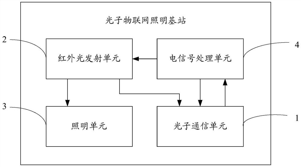
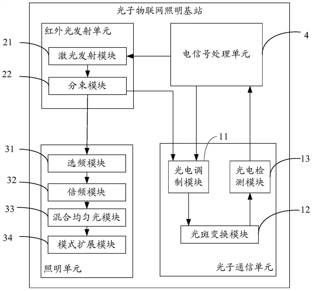
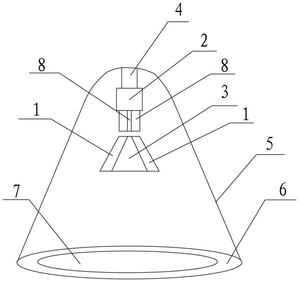
[0035] In this embodiment, a photonic IoT lighting base station is provided, such as Figure 1 to Figure 3 shown, including,

[0036] Infrared light emitting unit 2, used to emit infrared laser beams with a wavelength ranging from 1100 nm to 1700 nm;

[0037] The photonic communication unit 1 is used to transmit and receive laser signals with a ...


PUM

PropertyMeasurementUnit
wavelengthaaaaaaaaaa

Abstract

The invention discloses a photonic Internet of Things lighting base station, including a photonic communication unit for emitting and receiving laser signals in the communication band and performing photoelectric conversion; an infrared light emitting unit for emitting infrared laser beams in a characteristic wavelength range; a lighting unit, It is used to obtain the infrared laser beam from the infrared light emitting unit and convert it into white light illumination; the electrical signal processing unit is used to process the electrical signal from the photon communication unit, and provide electrical signals to the infrared light emitting unit and the photon communication unit, wherein the infrared The laser energy emitted by the light emitting unit is distributed to the lighting unit and the photonic communication unit according to a specific ratio. The photonic Internet of Things lighting base station provided by the present invention uses photonic communication, which reduces the capacity limitation and electromagnetic interference of electronic communication; due to the use of invisible light, the influence of visible light on the silicon-based integrated chip technology platform is avoided; at the same time, it is compatible with lighting lamps, from Fundamentally realize the construction of high-speed and safe Internet of Things.

Description

technical field [0001] This application relates to the technical field of the Internet of Things, and in particular to a lighting base station of the Photonic Internet of Things. Background technique [0002] The Internet of Things technology is the basic support technology platform of the information age. Large capacity, wide distribution, high reliability, high confidentiality and low radiation hazard are the basic requirements of the Internet of Things technology. [0003] The current Internet of Things technology is mainly based on the architecture of electronic signal connection. The disadvantages of the electronic Internet of Things include: (1) The evolution of large-capacity technology is difficult. Although 5G can provide ten times the communication speed of 4G, it is very difficult to continue to increase the baseband frequency of electronic communication, the cost is high, and the power consumption is huge; (2) Electromagnetic interference and radiation hazards t...

Claims


Application Information

Patent Timeline
Patent Type & Authority Patents(China)
IPC IPC(8): H04B10/114H04B10/50H04W88/08F21V9/00F21V5/04G02F1/35G02B27/10
CPCF21V5/046F21V9/00G02B27/1006G02F1/353H04B10/114H04B10/503H04W88/08
Inventor 周炆杰刘晓海
Owner OTN INTELLIGENT TECH (SUZHOU) CO LTD
Learn More