
OQPSK signal blind frequency offset estimation method based on differential constellation trajectory diagram

A frequency offset estimation and differential signal technology, applied in the field of frequency offset acquisition, can solve the problems of high complexity, poor real-time performance, and large frequency offset range of target equipment, and achieve the effect of rapid implementation and excellent performance.

Pending Publication Date: 2020-09-04
JIANGSU ELECTRIC POWER CO +1
View PDF0 Cites 0 Cited by
  • Summary
  • Abstract
  • Description
  • Claims
  • Application Information

AI Technical Summary

Problems solved by technology

Traditional frequency offset estimation algorithms are usually implemented through preambles or training sequences. When the frequency offset is large, frequency offset search and pre-compensation are required, which has high complexity and relatively poor real-time performance.
However, the passive radio frequency fingerprint identification system sometimes needs to work in a blind scenario, that is, only a small part of the parameter details are known to the transmitter, and the frequency offset range of the target device is large, and the real-time requirements are high. Therefore, a purely blind high real-time method to estimate carrier frequency offset

Method used


Image

  • OQPSK signal blind frequency offset estimation method based on differential constellation trajectory diagram
  • OQPSK signal blind frequency offset estimation method based on differential constellation trajectory diagram
  • OQPSK signal blind frequency offset estimation method based on differential constellation trajectory diagram

Examples


Embodiment approach

[0022] (1) Baseband signal acquisition

[0023] In this particular embodiment, the baseband signal It is the baseband spread spectrum chip signal of the OQPSK modulated signal sent by the CC2530 module in the 2.4GHz frequency band received by the receiving end, which complies with the IEEE 802.15.4 standard, that is

[0024]

[0025] in, Represents the transmitted OQPSK symbol samples, A represents the constant phase of the OQPSK symbol, Represents the phase corresponding to the transmitted symbol, where Satisfy Represents that there is no phase mutation.

[0026] In this specific implementation, the symbol rate of the ZigBee module , the receiver sampling rate , therefore, the sampling rate at the receiving end is the symbol rate of the target signal times, that is =5. Represents the frequency offset to be estimated between the transmitter and receiver, Represents the sampling interval at the receiving end, Represents the phase offset between the t...


PUM


Abstract

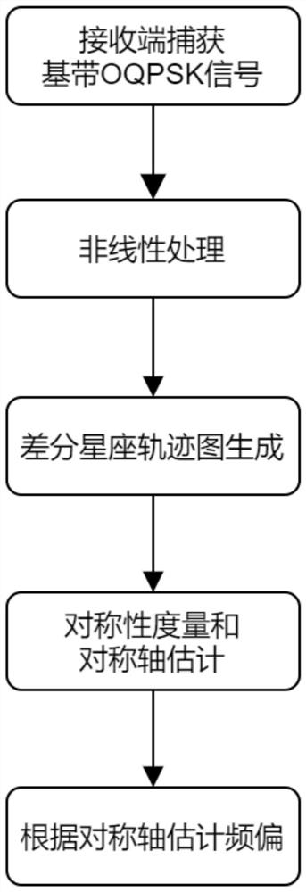
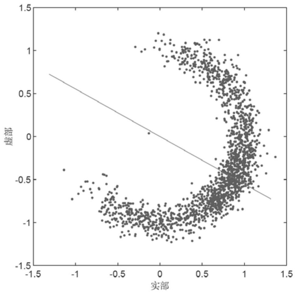
The invention discloses an OQPSK signal blind frequency offset estimation method based on a differential constellation trajectory diagram. The method comprises three parts of differential constellation trajectory diagram generation, symmetry axis estimation and frequency offset estimation. A receiving end knows the symbol rate of a signal, carries out even times of oversampling, and does not needinformation such as a training sequence to carry out synchronization processing. The receiving end carries out specific nonlinear processing on the received signals, then carries out differential processing according to a certain differential interval, and projects the signals to a complex plane to generate a plurality of differential constellation trajectory diagrams. Then, the receiving end performs symmetry axis estimation and symmetry measurement on each differential constellation trajectory diagram, and selects the symmetry axis of the differential constellation trajectory diagram with the best symmetry as a final symmetry axis estimation result. Finally, the receiving end obtains a frequency offset value of blind estimation based on the specific relationship between the symmetry axisand the frequency offset and the specific relationship between the differential interval and the sampling rate. The method can be used for frequency deviation estimation of systems adopting an OQPSKmodulation mode such as IEEE 802.15. 4 and the like.

Description

technical field [0001] The present application relates to the field of communication, and in particular to a method for acquiring frequency deviation of a communication system with OQPSK modulation mode. In addition, the present application can also be used in target recognition systems that need to obtain radio frequency fingerprint features of OQPSK communication systems. Background technique [0002] OQPSK modulation is a constant envelope digital modulation technology developed on the basis of QPSK. It staggers the code streams of the in-phase and quadrature branches by half a symbol period in time. Due to the offset of the half-period of the symbols in the two branches, only one path may be reversed in polarity each time, and the phenomenon that the polarities of the symbols in the two branches are reversed at the same time does not occur. Therefore, the OQPSK signal phase can only jump 0°, ±90°, and the 180° phase jump existing in QPSK modulation will not occur. [...

Claims


Application Information

Patent Timeline
IPC IPC(8): H04L27/227H04L27/00
CPCH04L27/0014H04L27/2273H04L2027/0024
Inventor 过烽梅沁李达华梁王佳瑜丁罕徐晓伟莫静泱虎啸沈超刘科可李双龙方昊
Owner JIANGSU ELECTRIC POWER CO
Learn More