
On-site high-precision heat treatment device for steam turbine blades

A heat treatment device, steam turbine blade technology, applied in heat treatment furnaces, heat treatment equipment, furnaces and other directions, can solve the problems of poor temperature uniformity, low efficiency, low precision, etc., to achieve clean temperature uniformity, no pollution, good temperature uniformity, heating large area effect

Pending Publication Date: 2020-09-08
XI AN JIAOTONG UNIV +1
View PDF0 Cites 2 Cited by
  • Summary
  • Abstract
  • Description
  • Claims
  • Application Information

AI Technical Summary

Problems solved by technology

This method uses a resistance band to wrap the entire welding area and heats it through the thermal resistance effect. The advantage is that the entire welding area can be heated. The disadvantage is that the heating speed is slow, the temperature uniformity is poor (plus or minus 20°C), and the low temperature section cannot control
[0007] In summary, the current methods of heat treatment after steam turbine blade repair have common shortcomings such as low precision, large errors, and low efficiency.
At the same time, there is no high-precision proprietary equipment in the world that can be applied to the post-repair heat treatment of steam turbine blades. In summary, it is very important to invent a set of post-repair heat treatment equipment with large heating area, high heating precision and no pollution. necessary

Method used


Image

  • On-site high-precision heat treatment device for steam turbine blades
  • On-site high-precision heat treatment device for steam turbine blades
  • On-site high-precision heat treatment device for steam turbine blades

Examples


Embodiment Construction

[0025] The present invention will be further described below in conjunction with the accompanying drawings.

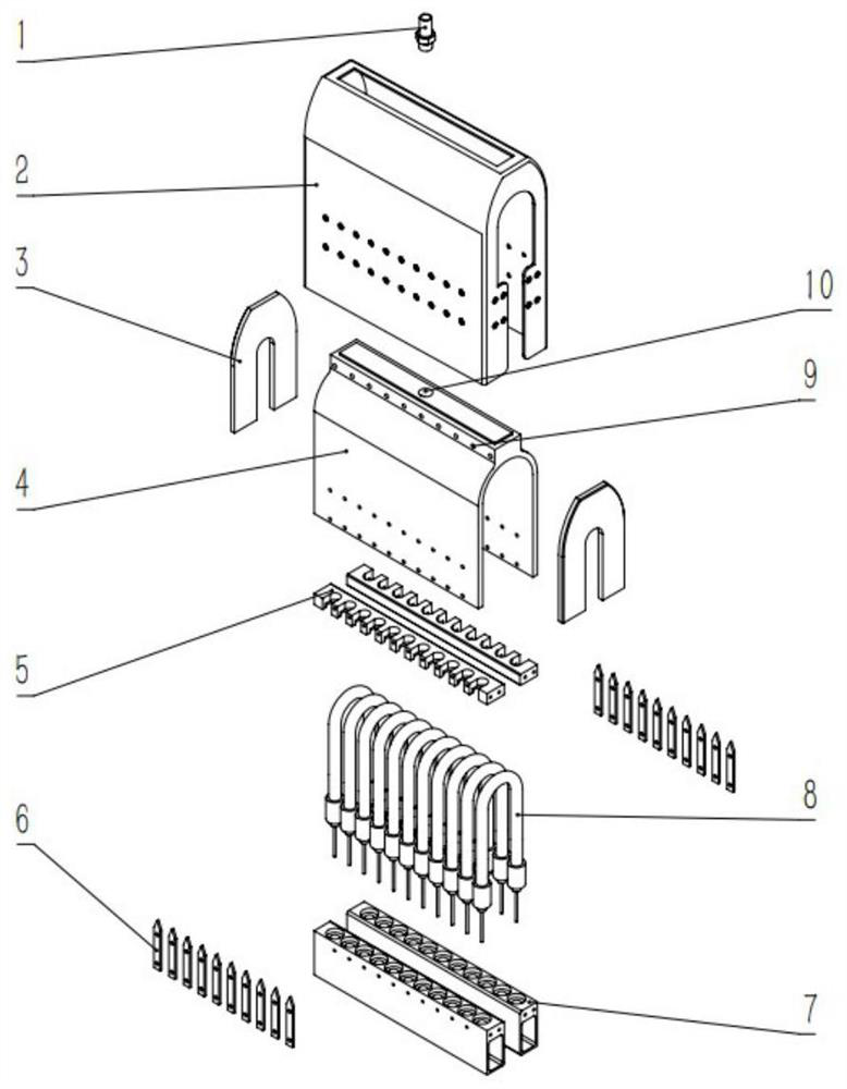
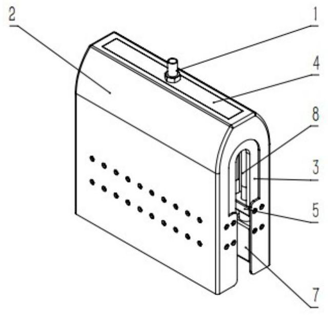
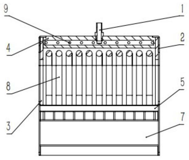
[0026] Such as Figure 1 to Figure 3 As shown, an on-site high-precision heat treatment device for steam turbine blades provided by the present invention is mainly composed of 10 parts: cooling pipe joint 1, infrared heater shell 2, end limit protection plate 3, infrared reflection-installation The base body 4, the upper fixture 5 of the infrared lamp tube, the shell mounting gasket 6, the lower fixture 7 of the infrared lamp tube, the infrared heating tube 8, the cooling port 9, and the joint installation hole 10.

[0027] In this device, the upper fixture 5 of the infrared lamp and the lower fixture 7 of the infrared lamp fix the infrared heating tube 8 in the infrared reflection-installation base 4 to form a heating space. The infrared heater shell 2 is welded to the top of the infrared reflection-mounting base 4, and the shell mounting gasket 6 is installed in the...


PUM


Abstract

The invention discloses an on-site high-precision heat treatment device for steam turbine blades. The device comprises an infrared heater shell, an infrared reflecting-mounting base mounted in the infrared heater shell in a sleeved mode and an infrared heating tube mounted in the infrared reflecting-mounting base through an infrared lamp tube fixture, wherein two ends of the infrared reflecting-mounting base pass through an end limiting protection plate used for protecting the infrared heating tube; a heating space is formed between the infrared heating tube and the infrared reflecting-mounting base, the top of the infrared reflecting-mounting base is provided with a joint mounting hole and a cooling pipeline joint, and the cooling pipeline joint communicates with the heating space; and the side wall of the infrared reflecting-mounting base is provided with a plurality of cooling openings which communicate with the heating space, and gaps which communicate with the cooling openings areformed in middle portions of two side faces of the infrared heater shell and the infrared reflecting-mounting base. The device has the advantages of being large in heating area, high in heating precision, good in temperature uniformity and clean without contamination.

Description

technical field [0001] The invention belongs to the technical field of heat treatment of steam turbine blades, and specifically relates to an on-site high-precision heat treatment device for steam turbine blades, especially suitable for the heat treatment process after welding and repairing of steam turbine blades. Compared with the resistance band-wrapped heating heat treatment device, the heating heat treatment device has the advantages of large heating area, high heating precision, good temperature uniformity, and cleanliness and pollution-free. Background technique [0002] Steam turbine is the core power equipment of modern thermal power plants. It is also used in metallurgical industry, chemical industry and ship power plant. It mainly drives turbine blades to do work through high temperature and high pressure steam. As a core power device in the energy field, its output power can range from tens to hundreds of megawatts, and the average cost exceeds 100 million yuan. ...

Claims


Application Information

Patent Timeline
IPC IPC(8): C21D9/50C21D1/34
CPCC21D1/34C21D9/50
Inventor 王铁军江鹏李定骏张建普
Owner XI AN JIAOTONG UNIV
Learn More