Snap-in block unit and revetment
A buckle-type, block-based technology, which is applied in coastline protection, sea area engineering, container cultivation, etc., can solve the problems of easy toppling and damage of blocks, and achieve the effects of not easy to warp, convenient to transport, and easy to splice
- Summary
- Abstract
- Description
- Claims
- Application Information
AI Technical Summary
Problems solved by technology
Method used
Image
Examples
Embodiment 1
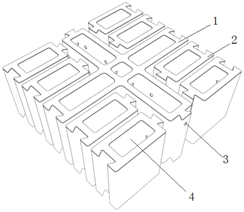
[0054] In this embodiment, a buckle-type block unit, such as figure 1 As shown, it includes a central block 1 and four groups of spliced blocks, and the central block 1 is a cross-shaped block; the four groups of spliced blocks can be respectively embedded in the four corners 11 of the central block 1; each group of spliced blocks It includes two clamping blocks 2; the clamping blocks 2 have a rectangular structure or an I-shaped structure.
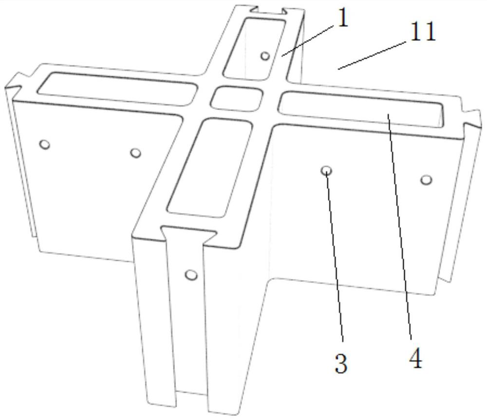
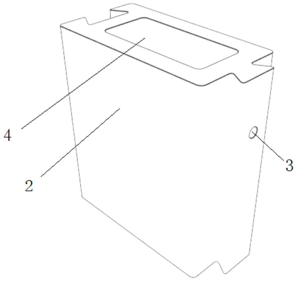
[0055] In order to make the splicing of the central block 1 and the clamping block 2 more reliable, the four end faces of the central block 1 in this embodiment are respectively provided with locking protrusions or locking grooves; figure 2 As shown, one of the pair of opposite ends on the center block 1 is a lock-type protrusion, and the other pair of opposite ends is a lock-type groove; image 3 As shown, the two opposite sides of each locking block 2 are respectively provided with protrusions and grooves. And a threading hole ...
Embodiment 2
[0059] Such as Figure 4 As shown, the structure of the buckle-type block unit of this embodiment is basically the same as that of the buckle-type block unit in Embodiment 1, the difference is that:
[0060]The snap-on block unit of this embodiment includes a central block 1 and five groups of spliced blocks, the central block 1 is a T-shaped block; one group of spliced blocks in the five groups of spliced blocks includes a snap-fit block 2. The clamping blocks 2 and the central block 1 form a cross-shaped structure; the other four groups of spliced blocks respectively include two clamped blocks 2; the other four groups of spliced blocks can be respectively embedded in four of the cross-shaped structures three corners 11; the three end faces of the T-shaped blocks and the T-shaped intersections are respectively provided with protrusions or grooves; the two opposite sides of each of the clamping blocks 2 are respectively provided with protrusions or grooves, The ce...
Embodiment 3
[0062] Such as Figure 5 As shown, the structure of the buckle-type block unit of this embodiment is basically the same as that of the buckle-type block unit in Embodiment 1 and Embodiment 2, the difference is that:
[0063] The snap-on block unit of this embodiment includes a central block 1 and six groups of spliced blocks, the central block 1 is a straight block; two groups of spliced blocks in the six groups of spliced blocks only include one block 2, the two groups of spliced blocks and the inline blocks form a cross-shaped structure; the remaining four groups of spliced blocks all include two clamped blocks 2, and the four groups of spliced blocks can be respectively embedded in the cross-shaped structure. The four corners 11; the two end faces of the inline block and both sides of the middle part are respectively provided with protrusions or grooves; the two opposite sides of each said clamping block 2 are respectively provided with protrusions or grooves, ...
PUM
 Abstract
Description
Claims
Application Information
 - R&D
- Intellectual Property
- Life Sciences
- Materials
- Tech Scout
- Unparalleled Data Quality
- Higher Quality Content
- 60% Fewer Hallucinations
Browse by: Latest US Patents, China's latest patents, Technical Efficacy Thesaurus, Application Domain, Technology Topic, Popular Technical Reports.
© 2025 PatSnap. All rights reserved.Legal|Privacy policy|Modern Slavery Act Transparency Statement|Sitemap|About US| Contact US: help@patsnap.com


